Distribution of material discharged from a rotary mower

a technology of material discharge and rotary mower, which is applied in the direction of mowers, agricultural tools and machines, agriculture, etc., can solve the problem that the utility of mowers for cutting vegetation is limited

Inactive Publication Date: 2009-08-06
HOFMANN TODD +1
View PDF7 Cites 13 Cited by
  • Summary
  • Abstract
  • Description
  • Claims
  • Application Information

AI Technical Summary

Benefits of technology

[0012]In a first embodiment the present invention provides a rotary mower apparatus comprising a mower deck, and a mower blade rotatably mounted under the mower deck about a substantially vertical axis of rotation. The mower blade follows a circular path having a radius equal to a cutting radius, and a baffle plate extends downward from the mower deck adjacent to the circular path and outside the circular path. A vertical position of a bottom edge of the baffle plate can be adjusted from a lowered position to a raised position.
[0013]In a second embodiment the present invention provides a rotary mower apparatus comprising a mower deck, and a mower blade rotatably mounted under the mower deck about a substantially vertical axis of rotation. A deflector plate has a front edge pivotally mounted about a substantially horizontal pivot axis to the mower deck rearward of the mower blade such that the deflector plate extends downward and rearward from the front edge thereof, and such that the deflector plate can pivot in a pivot range from a lowered position to a raised position. A support mechanism is operative to support the deflector plate at a selected location in the pivot range.

Problems solved by technology

In the prior art where the baffle plates are fixed, the mower has limited utility for cutting vegetation other than that for which the baffle plates are configured.

Method used


Image

  • Distribution of material discharged from a rotary mower
  • Distribution of material discharged from a rotary mower
  • Distribution of material discharged from a rotary mower

Examples


Embodiment Construction

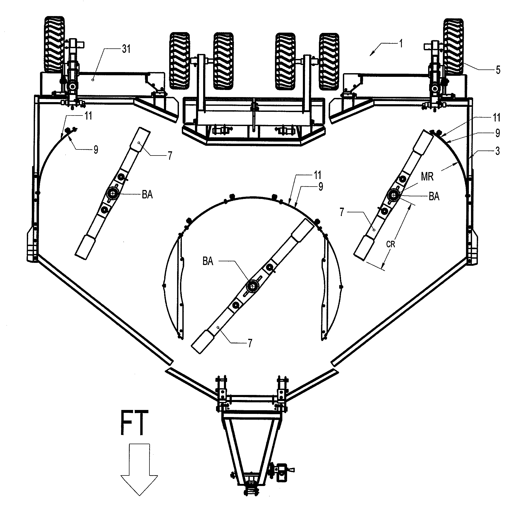
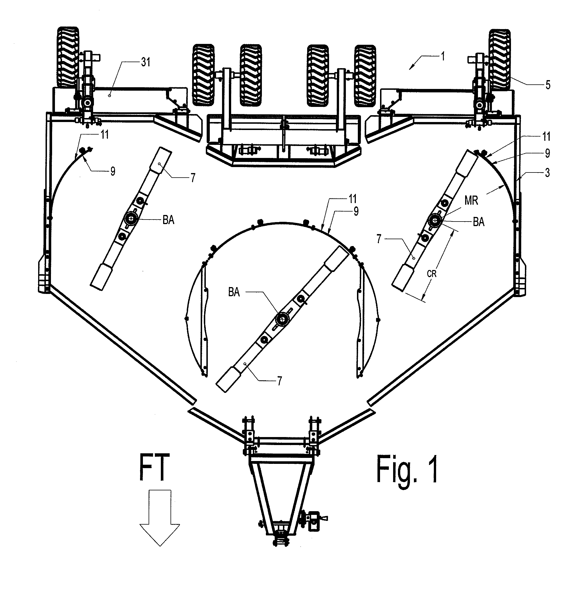
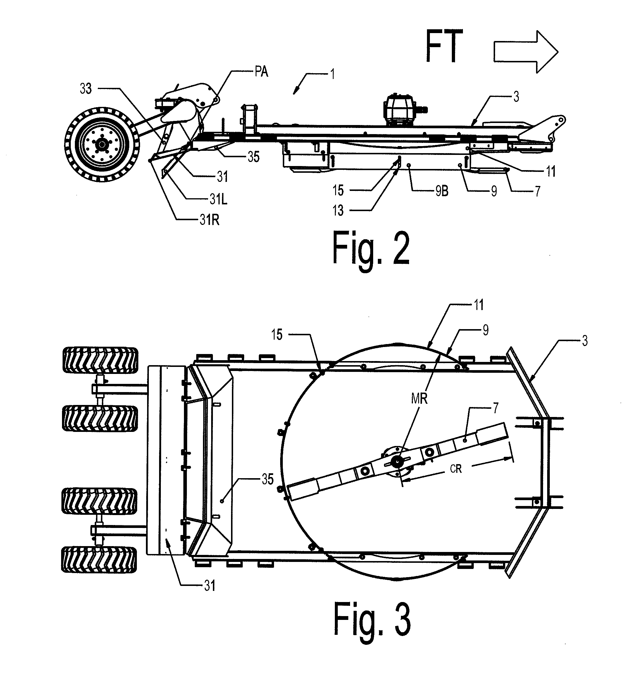
[0024]FIG. 1 illustrates a schematic bottom view of an embodiment of a rotary mower apparatus 1 of the present invention. FIG. 2 is a schematic side view of the apparatus 1, and FIG. 3 is schematic bottom view of one mower deck of the apparatus 1. The apparatus 1 comprises a mower deck 3 supported by rear wheels 5 and a hitch at a front end thereof adapted for attachment to a towing vehicle for operating movement in a forward travel direction FT. A plurality of mower blades 7 are rotatably mounted under the mower deck 3 about substantially vertical axes of rotation BA. The mower blades follow a circular path having a radius equal to a cutting radius CR.

[0025]A baffle plate 9 extends downward from the mower deck 3 adjacent to the circular path and outside the circular path such that the baffle plate is not contacted by the blade 7 as the blade 7 rotates, but such that the baffle plate 9 is in close proximity to the end of the blade 7. In the illustrated embodiment a mounting plate 11...


PUM


Abstract

A rotary mower apparatus includes a mower deck, and a mower blade rotatably mounted under the mower deck about a substantially vertical axis of rotation. The mower blade follows a circular path having a radius equal to a cutting radius, and a baffle plate extends downward from the mower deck adjacent to and outside the circular path. A vertical position of a bottom edge of the baffle plate can be adjusted from a lowered position to a raised position. A deflector plate can be attached such that a front edge thereof is pivotally mounted to the mower deck rearward of the mower blade such that the deflector plate extends downward and rearward from the front edge thereof, and such that the deflector plate can pivot a lowered to a raised position and be supported at a selected location in the pivot range.

Description

CROSS REFERENCE TO RELATED APPLICATIONS[0001]This application is a divisional application of U.S. application Ser. No. 12 / 179,085, filed Jul. 24, 2008 (which is hereby incorporated by reference).FIELD OF THE INVENTION[0002]This invention is in the field of rotary mowers and in particular concerns improving the distribution of material cut by such mowers.BACKGROUND OF THE INVENTION[0003]Rotary mowers are used for cutting a wide variety of vegetation. Vegetation in roadside ditches is cut to provide visibility for motorists, prevent blowing snow from being trapped, and like reasons. The distribution of the cut material discharged from the mower is not usually of great concern, so long as it is not left in unsightly piles.[0004]It is also becoming more popular to use rotary mowers in the agricultural industry to shred crop residue. Modern agricultural practices tend toward reducing tillage, such that it is no longer desirable to plow crop residue into the soil. Depending on the crop an...

Claims


Application Information

Patent Timeline
Patent Type & Authority Applications(United States)
IPC IPC(8): A01D34/82A01D34/81
CPCA01D34/667A01D34/86A01D34/828A01D34/71
Inventor HOFMANN, TODDSIROSKI, BRIAN
Owner HOFMANN TODD
Why Eureka
Try Eureka