Pneumatic tire with composite bead core

a technology of composite bead core and pneumatic tire, which is applied in the direction of tire beads, vehicle components, transportation and packaging, etc., can solve the problems of one or more of the elongated elements of the tire bead core breaking, and achieve the effect of suitably increasing the hooping force of the tire beads on the rim, without negatively affecting the mechanical properties of the tire beads and the overall tire uniformity

Inactive Publication Date: 2009-08-06
PIRELLI TYRE SPA
View PDF10 Cites 17 Cited by
  • Summary
  • Abstract
  • Description
  • Claims
  • Application Information

AI Technical Summary

Benefits of technology

[0026]The Applicant has found that the hooping force of the tire beads on the rim can be suitably increased—without negatively affecting the mechanical properties of the tire beads and the overall tire uniformity—by providing the tire with bead cores which include metal elongated elements and carbon fiber elongated elements.

Problems solved by technology

However, the use of levers acting on the elongated elements forming the bead core may result in locally exceeding the elastic strain limits of said elements which is particularly undesirable since it may have a negative effect on the structural strength properties of the bead core during the travel of the tire and, in some cases, may also result in breakage of one or more of the elongated elements of the tire bead core.

Method used


Image

  • Pneumatic tire with composite bead core
  • Pneumatic tire with composite bead core
  • Pneumatic tire with composite bead core

Examples


first embodiment

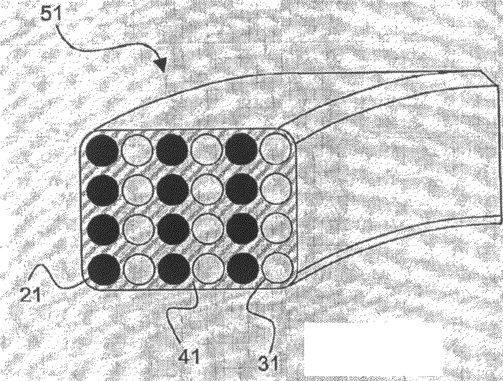
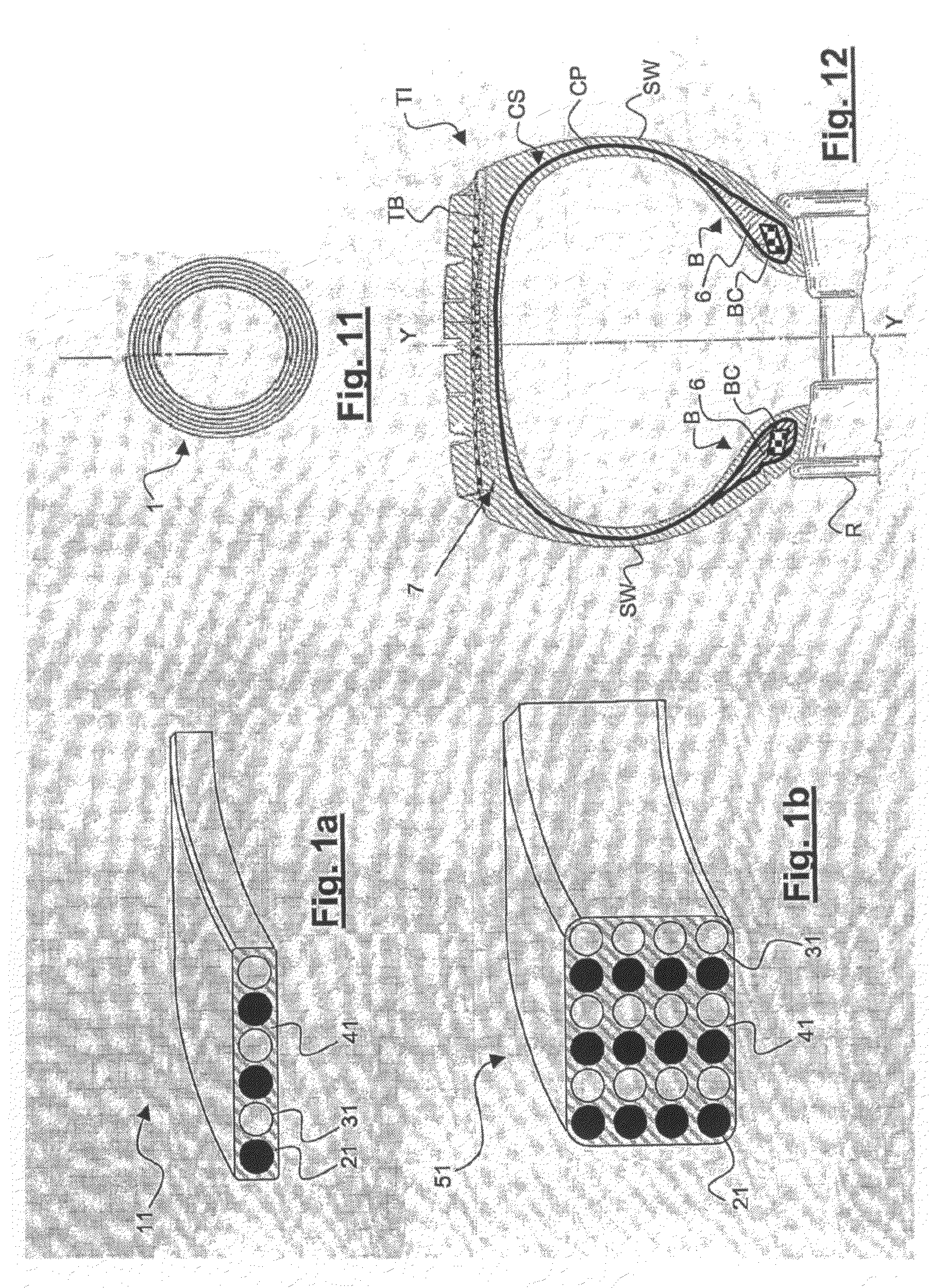
[0052]FIGS. 1a, 1b and 11 show a first embodiment of the present invention. In particular, FIG. 1a shows a portion of a bead core strip element 11. The strip element 11 comprises a plurality of axially adjacent elongated elements 21, 31 which are embedded in an elastomeric material 41. As schematically represented in FIG. 11, a bead core 51 (partially shown in FIG. 1b) is obtained by spirally winding (coiling) the strip element 11 to form a plurality of layers, the latter being radially superimposed one to the other to form the bead core 51. In FIG. 11 the wound strip element to obtain a plurality of radially superimposed layers has been indicated with reference number 1.

[0053]The term “adjacent”, as used in the present description and claims, may or may not imply contact but always implies absence of anything of the same kind between. Two elongated elements are considered to be adjacent one to the other either if they are in contact (at least partially) or if they are not in contac...

second embodiment

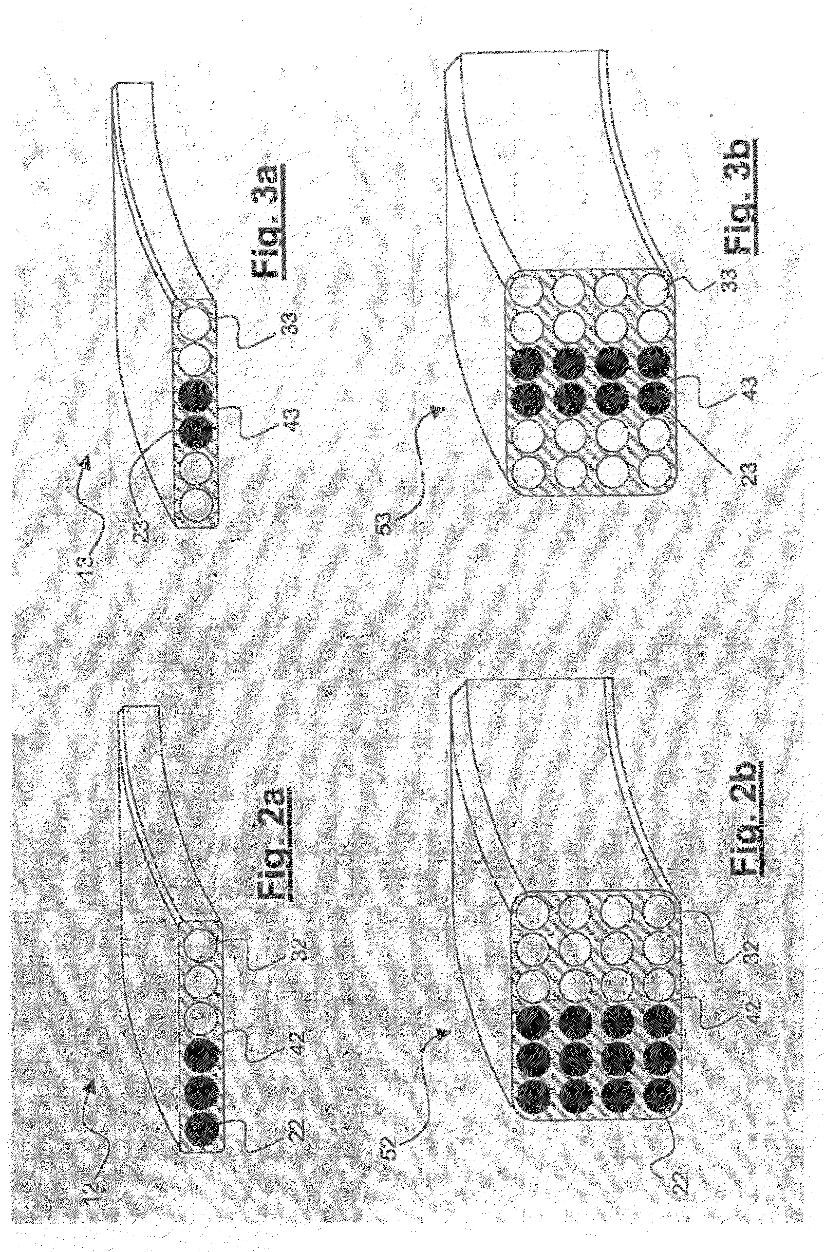
[0076]FIGS. 2a and 2b show a portion of a bead core strip element 12 and a bead core 52, respectively, according to a second embodiment of the present invention.

[0077]The bead core strip element 12 shown in FIG. 2a comprises a plurality of axially adjacent elongated elements 22, 32 which are embedded in an elastomeric material 42. In details, the bead core strip element 12 comprises three second elongated elements 22 made of carbon fibers and three first metal elongated elements 32.

[0078]As schematically represented in FIG. 11 and as already described with reference to the first embodiment of the present invention, the bead core 52 (partially shown in FIG. 2b) is obtained by spirally winding (coiling) the strip element 12 to form a plurality of layers radially superimposed to each other. In FIG. 11 the wound strip element to obtain a plurality of radially superimposed layers has been indicated with reference number 1.

[0079]The bead core 52 shown in FIG. 2b is a 6×4 “Alderfer” bead c...

third embodiment

[0086]FIGS. 3a and 3b show a portion of a bead core strip element 13 and a bead core 53, respectively, according to a third embodiment of the present invention.

[0087]The bead core strip element 13 shown in FIG. 3a comprises a plurality of axially adjacent elongated elements 23, 33 which are embedded in an elastomeric material 43. In details, the bead core strip element 13 comprises two second elongated elements 23 made of carbon fibers and four first metal elongated elements 33.

[0088]As schematically represented in FIG. 11 and as already described with reference to the first embodiment of the present invention, the bead core 53 (partially shown in FIG. 3b) is obtained by spirally winding (coiling) the strip element 13 to form a plurality of layers radially superimposed to each other. In FIG. 11 the wound strip element to obtain a plurality of radially superimposed layers has been indicated with reference number 1.

[0089]The bead core 53 shown in FIG. 3b is a 6×4 “Alderfer” bead core ...


PUM


Abstract

A tire includes a carcass structure including at least one carcass ply, the carcass structure including a crown portion and two axially opposite side portions terminating in beads for mounting the tire on a rim; a tread band; and a belt structure interposed between the carcass structure and the tread band. The bead includes a bead core. The bead core includes: at least one first elongated element including at least one metal wire, and at least one second elongated element including at least one carbon fiber. The bead core results in an increased bead, forcing an improved bead unseating resistance and a decreased weight.

Description

BACKGROUND OF THE INVENTION[0001]1. Field of the Invention[0002]The present invention relates to a tire for a motor vehicle which is provided with an improved bead core.[0003]In particular, the present invention relates to a tire for a motor vehicle which is provided with a bead core suitable for ensuring an improved anchoring thereof to a wheel rim on which the tire is mounted.[0004]2. Description of the Prior Art[0005]A tire generally comprises: a carcass structure comprising at least one carcass ply; a tread band in a position radially external to the carcass structure; a belt structure interposed between the carcass structure and the tread band. A tire generally further comprises a pair of sidewalls applied to the carcass structure in axially opposite positions. The ends of the at least one carcass ply are folded back or secured to two annular reinforcing elements, i.e. the so-called “bead cores”, and the tire region which comprises the bead core is known as “tire bead”.[0006]Ge...

Claims


Application Information

Patent Timeline
Patent Type & Authority Applications(United States)
IPC IPC(8): B60C15/024
CPCB60C15/04B60C15/00
Inventor DAGHINI, GUIDOALMONACIL, CELINEBIZZI, STEFANOSUSA, ALESSANDRO
Owner PIRELLI TYRE SPA
Why Eureka
Try Eureka