Thermal processing furnace

a technology of thermal processing furnace and heating element, which is applied in the direction of muffle furnace, furnace heating element, furnace, etc., can solve the problems of heating element likely deformation, creeping strain on heating element, and slow increase in length

Active Publication Date: 2009-08-06
TOKYO ELECTRON LTD
View PDF7 Cites 27 Cited by
  • Summary
  • Abstract
  • Description
  • Claims
  • Application Information

AI Technical Summary

Benefits of technology

[0018]According to the present invention, since the support member is disposed on the inner circumferential surface of the heat insulation member, the support member supporting the heating resistor such that the heating resistor can be thermally expanded and thermally shrunk, and the movement prevention member is disposed on the heating resistor to be in contact with one side surface of the support member so as to prevent a downward movement of the heating resistor, the downward movement of the heating resistor can be prevented while allowing a radial movement of the heating resistor caused by the thermal expansion and the thermal shrinkage, to thereby improve a durability of the thermal processing furnace including the heating resistor.

Problems solved by technology

However, by using the heating element under a high temperature, the heating element undergoes a creep strain, and slowly increases in length over time.
Due to the repeated rise and drop in temperature, the heating element is likely to be deformed.
This may generate a short-circuit between adjacent parts of the deformed heating element, which may invite disconnection.
Thus, there is a possibility that a short-circuit occurs between a part and another part adjacent thereto of the heating element, resulting in some disconnection by a heat of a spark generated upon the short-circuit.
In this case, it can be considered that a stress tends to concentrate on the joined portion of the fixing member fixed on the heating resistor, which entails deterioration in durability (reduction in lifetime) of the heating resistor.
Further, since the fixing member has a bar-like shape, the fixing member may easily drop out of the heat insulation member, whereby it is difficult to secure a sufficient holding force of the heating resistor, which may deteriorate the durability of the heating resistor.

Method used


Image

  • Thermal processing furnace
  • Thermal processing furnace
  • Thermal processing furnace

Examples


Embodiment Construction

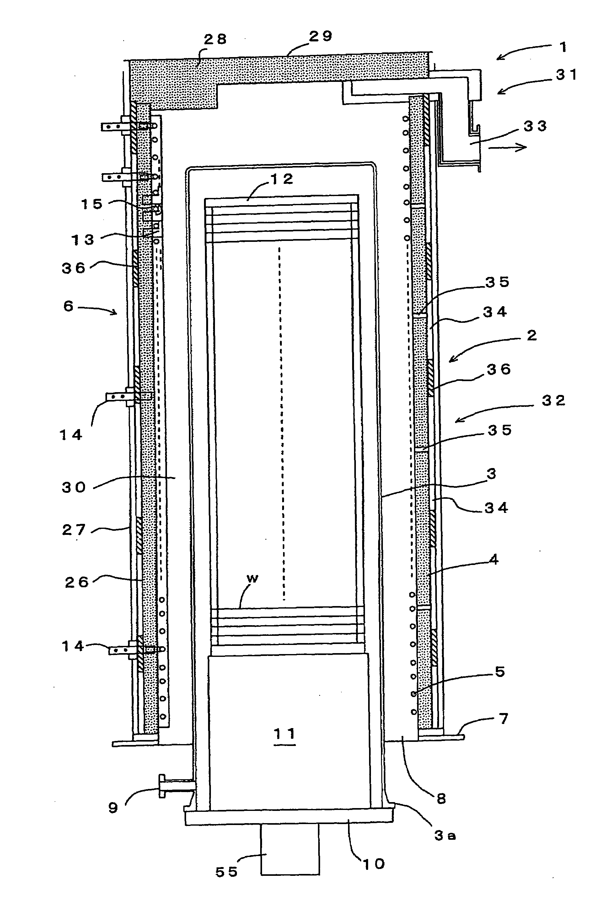
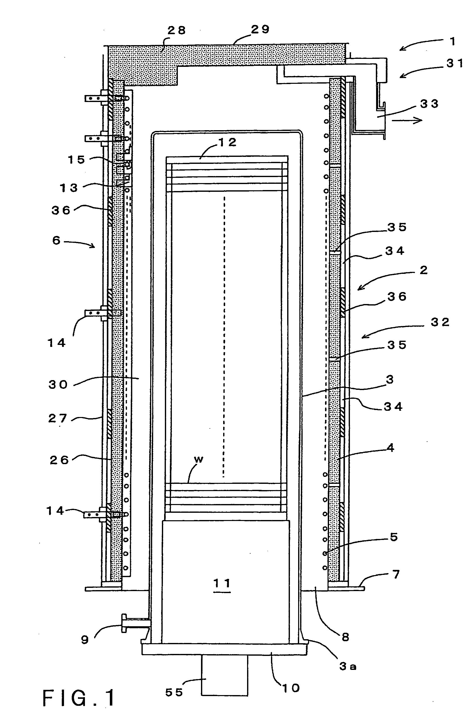
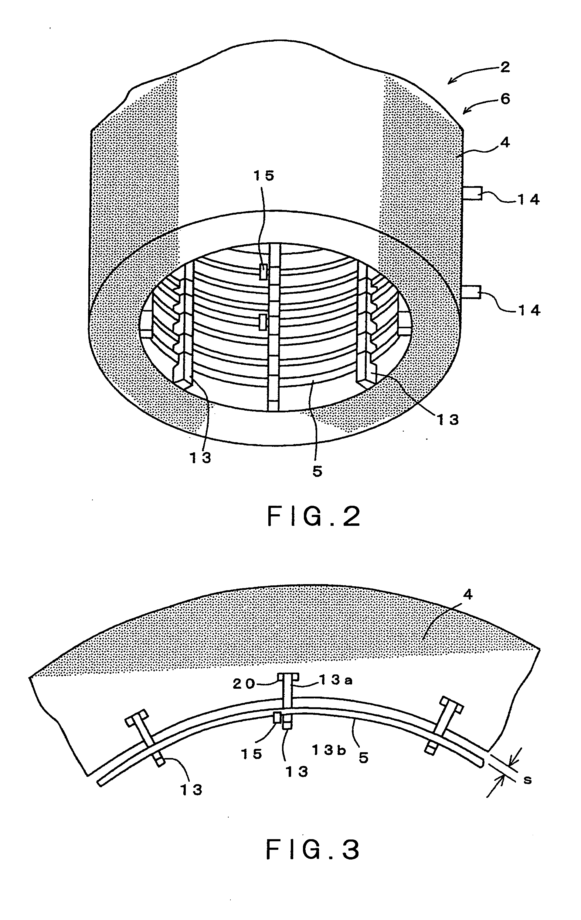
[0030]The mode for carrying out the present invention will be described herebelow with reference to the accompanying drawings. FIG. 1 is a longitudinal sectional view schematically showing an embodiment of a thermal processing furnace of the present invention. FIG. 2 is a perspective view showing a part of the thermal processing furnace. FIG. 3 is a partial cross-sectional view showing the thermal processing furnace. FIG. 4 is a partial longitudinal sectional view showing the thermal processing furnace.

[0031]In FIG. 1, the reference number 1 depicts a vertical-type thermal processing apparatus which is one of semiconductor manufacturing apparatuses. The thermal processing apparatus 1 has a vertical-type thermal processing furnace 2 capable of simultaneously receiving a number of objects to be processed such as semiconductor wafers w, and subjecting thereto thermal processes such as an oxidation process, a diffusion process, a reduced-pressure CVD process, and so on. The thermal proc...


PUM


Abstract

A thermal processing furnace comprises: a tubular heat insulation member 4 surrounding a processing vessel 3 for receiving and thermally processing an object to be processed w; a heating resistor 5 helically arranged on an inner circumferential surface of the heat insulation member 4; and a support member 13 disposed on the inner circumferential surface of the heat insulation member 4, the support member 13 supporting the heating resistor 5 such that the heating resistor 5 can be thermally expanded and thermally shrunk. The thermal processing furnace further comprises: a movement prevention member 15 disposed on the heating resistor 5 to be in contact with one side surface of the support member 13 so as to prevent a downward movement of the heating resistor 5.

Description

CROSS REFERENCE TO RELATED APPLICATIONS[0001]This application is based upon and claims the benefit of priority from the prior Japanese Patent Application No. 2008-021231 filed on Jan. 31, 2008, the entire contents of which are incorporated herein by reference.FIELD OF THE INVENTION[0002]The present invention relates to a thermal processing furnace for thermally processing an object to be processed received therein.BACKGROUND ART[0003]In a manufacturing method of a semiconductor device, various thermal processing apparatuses are used for subjecting an object to be processed, which is a semiconductor wafer, to an oxidation process, a diffusion process, a CVD (Chemical Vapor Deposition) process, and so on. A general thermal processing apparatus includes a thermal processing furnace that is composed of a processing vessel (reaction tube) configured to receive a semiconductor wafer and to thermally process the same, a heating resistor disposed around the processing vessel, and a heat ins...

Claims


Application Information

Patent Timeline
Patent Type & Authority Applications(United States)
IPC IPC(8): H05B3/06
CPCF27B17/0025F27D11/02H05B3/08H01L21/67109F27D99/0006H01L21/02H01L21/205H01L21/324
Inventor KOBAYASHI, MAKOTOYAMAGA, KENICHINAKAO, KEN
Owner TOKYO ELECTRON LTD
Why Eureka
Try Eureka