
Coreless rubber crawler and traveling device

a technology of traveling device and crawler, which is applied in the direction of endless track vehicles, mechanical devices, transportation and packaging, etc., can solve the problems of reducing the life of the crawler, affecting the performance of the crawler, so as to reduce the damage to the rubber protrusion, reduce the surface pressure, and reduce the damage

Inactive Publication Date: 2009-08-06
BRIDGESTONE CORP
View PDF10 Cites 18 Cited by
  • Summary
  • Abstract
  • Description
  • Claims
  • Application Information

AI Technical Summary

Benefits of technology

[0009]The raised step portions and the linear groove are formed at the rubber crawler, and the engaging portion of the sprocket is made to be a length that spans the entire length of the linear groove formed between the raised step portions and the rubber protrusion base portions. In other words, a structure is provided in which the engaging portion of the sprocket which transmits driving force with respect to the rubber crawler engages with not only the base portions of the rubber protrusions but also with the linear groove. Due to this, application of an unexpected load to the rubber protrusions is prevented, resulting in lowering of surface pressure to the rubber protrusions, and large deformation of the rubber protrusions is eliminated, whereby damage to the rubber protrusions can be reduced.
[0010]The present applicant has already provided a rubber crawler in which raised step portions are formed to the left and right directions of rubber protrusions (refer to Japanese Patent Application Laid-Open (JP-A) No. 11-198871).
[0011]The content of this previous proposal is a rubber crawler in which a core and steel cords serving as a tensile material are buried, wherein a pair of protrusions protruding from the core toward an inner circumferential side of the rubber crawler are formed. In the rubber crawler, raised step portions serving as a wheel traveling surface are provided at the left and right width directions of the protrusions, the raised step portions are disposed in a zigzag shape in the longitudinal direction of the rubber crawler, and a mud draining groove is formed between the raised step portions.
[0012]In the invention of the aforementioned previous proposal, the raised step portions form the zigzag shape in the longitudinal direction of the rubber crawler for the purpose of preventing vibration originating at a wheel. The mud draining groove is formed accompanying the raised step portions and is provided for mud draining, and since the mud draining groove is also formed in a zigzag shape, this is not a structure in which a sprocket pin engages therewith.
[0013]The rubber crawler of the present invention is a coreless rubber crawler having rubber protrusions for driving at an inner circumferential surface thereof, wherein raised step portions are provided to both of left and right sides corresponding to the rubber protrusions, and a space between step portions that are adjacent to each other in the longitudinal direction of the rubber crawler is made to be a linear-shaped groove that is continuous across the width direction of the crawler while matching with (corresponding to) base portions of the rubber protrusions.
[0014]Since the base portions of the rubber protrusions and the linear-shaped groove are configured to engage with a sprocket pin, when the rubber crawler which is mounted at a machine body is seen in side view, it is necessary for the base portions of the rubber protrusions and the linear-shaped groove to form one continuous linear shape. In the coreless rubber crawler traveling device of the second aspect of the present invention, the relationship between the coreless rubber crawler and the sprocket is such that, with respect to the base portions of the rubber protrusions and the linear groove which form a continuous linear shape, the sprocket comprises a pin formed at the same pitch as the rubber protrusions and it is preferable that a length of the pin is made to be a length that spans the entire length of the linear groove formed between the raised step portions, and the rubber protrusion base portions. When the rubber crawler is driven, the pin engages in a form so as to be buried in the groove and engages not only with the base portions of the rubber protrusions, but also simultaneously with the linear groove. Due to this, application of an unexpected load to the rubber protrusions is prevented, resulting in elimination of large deformation of the rubber protrusions, and damage to the rubber protrusions can be reduced.

Problems solved by technology

As a result, for example, in uphill traveling on a steeply inclined surface or the like, there are times when an unexpectedly large force is applied to the rubber protrusions from the outside, and since the direction of the applied force is not constant, there are cases where, according to the circumstances, great deformation is caused at the rubber protrusions, engagement with the sprocket is not achieved, and a so-called tooth skipping phenomenon occurs.
When this tooth skipping phenomenon occurs often, not only is vibration caused at the machine body, but there are cases where this leads to destruction of the rubber protrusions, and this can cause shortening of the lifespan of the rubber crawler.
Further, even at the time of ordinary traveling, driving force is constantly applied to the rubber protrusions from the sprocket.
As a result, there are also cases where the rubber protrusions are damaged (generation of cracks, loss of a part of rubber, or the like), whereby the lifetime of the rubber crawler may be shortened.

Method used


Image

  • Coreless rubber crawler and traveling device
  • Coreless rubber crawler and traveling device
  • Coreless rubber crawler and traveling device

Examples


Embodiment Construction

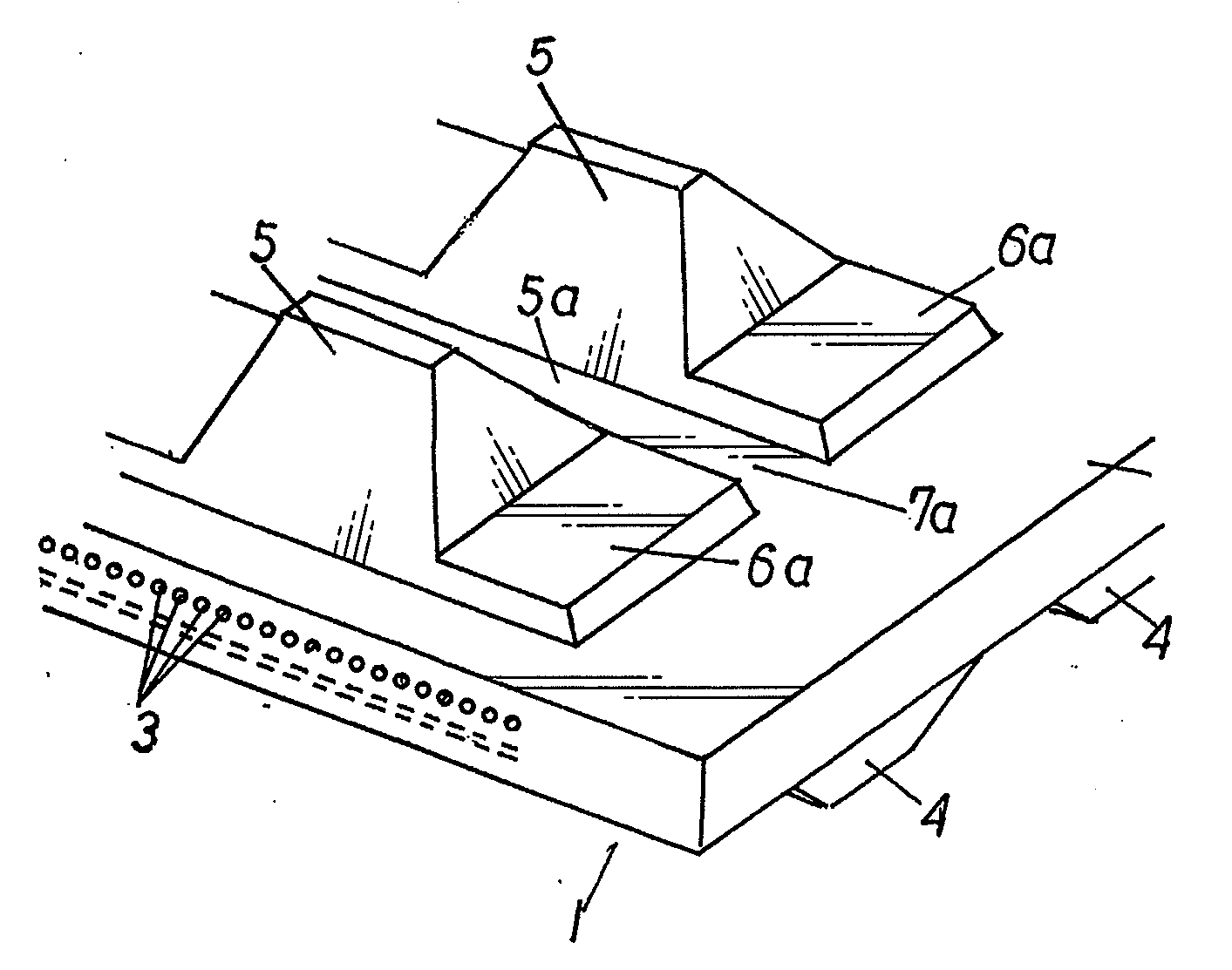
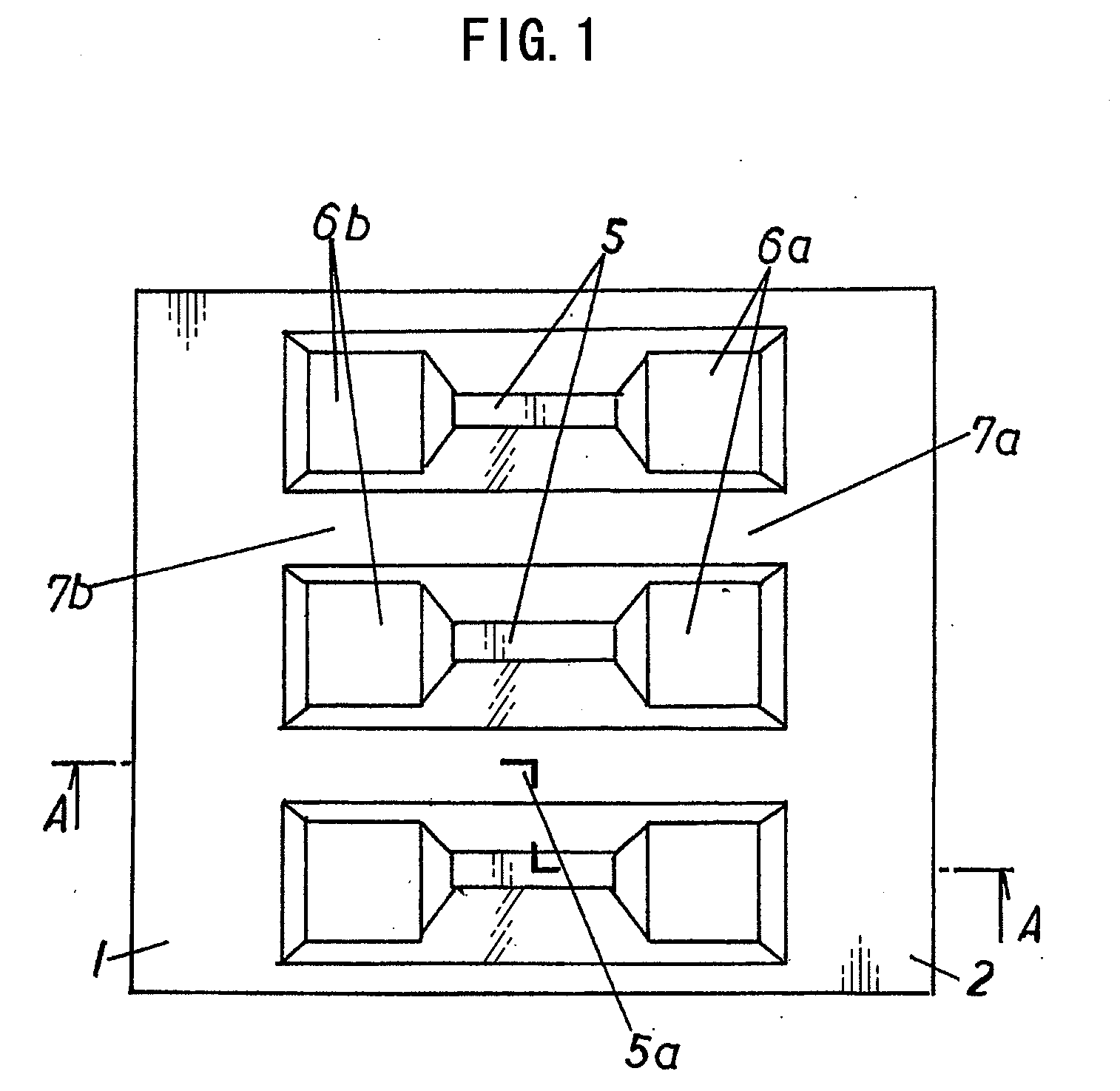
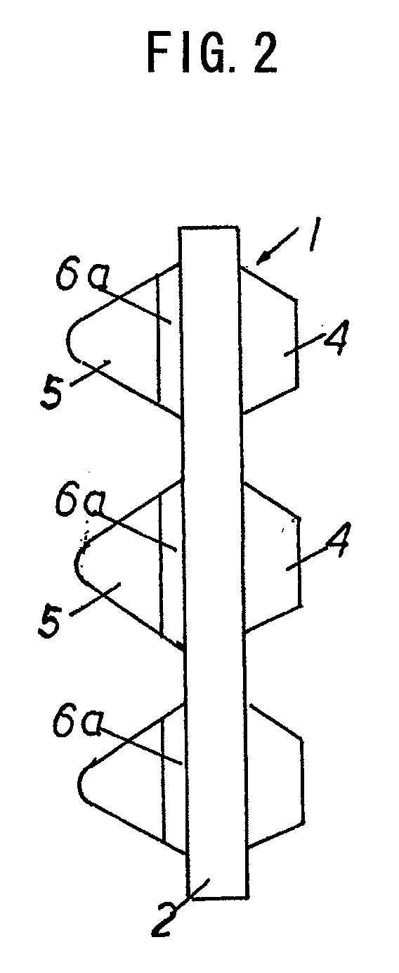
[0023]Hereinafter, an embodiment of the present invention will be described in further detail by way of the drawings. FIG. 1 is a plan view of an inner circumferential side of the coreless rubber crawler of the first aspect of the present invention, FIG. 2 is a side view, FIG. 3 is a cross-sectional view along a line A-A in FIG. 1, and FIG. 4 is a perspective view. In the drawings, reference numeral 1 indicates a coreless rubber crawler, and the coreless rubber crawler is continuous in the up-down direction of the page in FIG. 1 with an endless rubber elastic body 2 serving as a substrate. Reference numeral 3 indicates steel cords serving as a tensile material buried in the rubber elastic body 2 in the longitudinal direction thereof. Further, lugs 4 are formed at an outer circumferential surface of the rubber elastic body 2, and rubber protrusions 5 are formed at the center of the inner circumferential surface at a constant pitch. At the left and right of the rubber protrusions 5 in...


PUM


Abstract

The present invention provides a rubber crawler in which tooth skipping does not occur even if a large load acts on a rubber protrusion (5), and in which surface pressure on the rubber protrusion (5) is reduced. The coreless rubber crawler includes an endless rubber elastic body, a tensile material (3) buried in the longitudinal direction thereof, a rubber lug (4) formed at an outer circumferential surface of the rubber elastic body, and rubber protrusions (5) further formed at an inner circumferential surface of the rubber elastic body at a constant pitch in the longitudinal direction thereof, wherein raised step portions (6a) are formed to the right and left of the rubber protrusions (5) in the width direction of the rubber crawler, and a linear groove (7a) is formed between raised step portions that are adjacent to each other in the longitudinal direction of the rubber crawler so as to be continuous to base portions of the rubber protrusions when the rubber elastic body is seen in side view.

Description

TECHNICAL FIELD[0001]The present invention relates to improvement of rubber protrusions provided for driving of a coreless rubber crawler.BACKGROUND ART[0002]A coreless rubber crawler is used for relatively high-speed traveling and adopts a system in which rubber protrusions that are formed at a constant pitch at the center of an inner circumferential surface of the rubber crawler and a sprocket that is provided at a machine body side engage with each other to transmit driving force to the rubber crawler.[0003]As a result, for example, in uphill traveling on a steeply inclined surface or the like, there are times when an unexpectedly large force is applied to the rubber protrusions from the outside, and since the direction of the applied force is not constant, there are cases where, according to the circumstances, great deformation is caused at the rubber protrusions, engagement with the sprocket is not achieved, and a so-called tooth skipping phenomenon occurs. When this tooth skip...

Claims


Application Information

Patent Timeline
Patent Type & Authority Applications(United States)
IPC IPC(8): B62D55/24B62D55/08
CPCB62D55/12B62D55/244B62D55/14
Inventor UCHIDA, SHINJI
Owner BRIDGESTONE CORP
Learn More