Linear actuator

a technology of linear actuators and actuators, applied in the direction of mountings, dynamo-electric machines, instruments, etc., can solve the problems of low magnetic force generated between them, low operability, and decrease in durability, so as to reduce the weight of the actuator, simplify the configuration, and reduce the effect of parts coun

Inactive Publication Date: 2009-08-06
HOYA CORP
View PDF9 Cites 19 Cited by
  • Summary
  • Abstract
  • Description
  • Claims
  • Application Information

AI Technical Summary

Benefits of technology

[0008]According to the above described configuration, the multipolar magnet comprises an integrally formed isotropic magnet material which is magnetized into S-poles and N-poles alternately along the axial direction thereof, and in this regard, the multipolar magnet may comprise a multipolar magnetized magnet of a rod-shaped isotropic magnet material formed with a plurality of magnetized regions each of which is magnetized into S-pole and N-pole as their respective two poles at a necessary pitch d

Problems solved by technology

However, its operability is extremely low since the permanent magnets are required to be kept holding radially and axially upon positioning until the adhesive becomes hard for adhering them.
In addition, when the adhesive force is weak, problems such as occurrence of displacement and bending deformation, and decreasing in durability caused by loss of faying condition by deterioration of adhesive agent.
However, because of existence of a pipe being outside of the permanent magnet, the permanent magnets cannot come very close to the surro

Method used


Image

  • Linear actuator
  • Linear actuator
  • Linear actuator

Examples


first embodiment

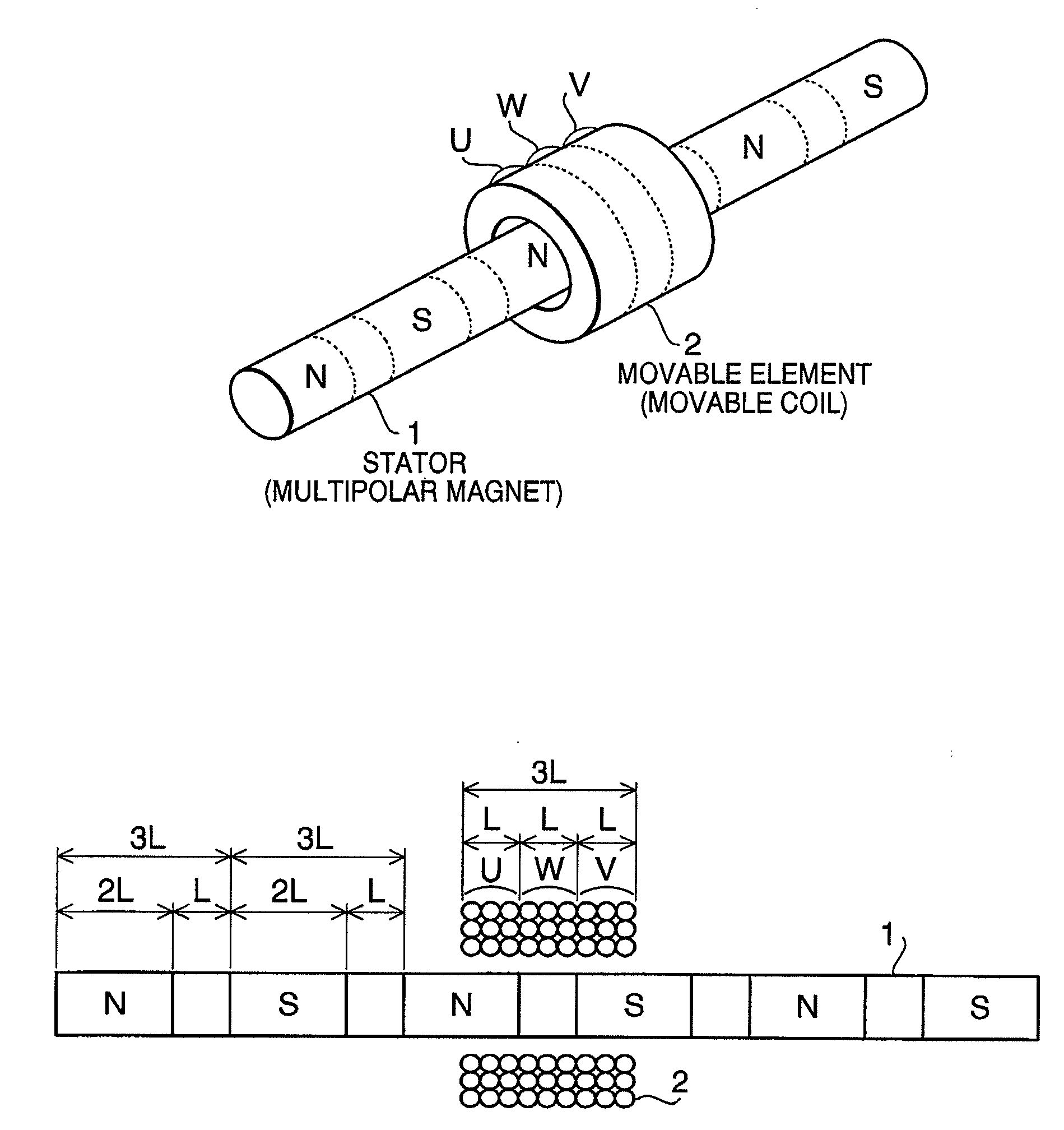
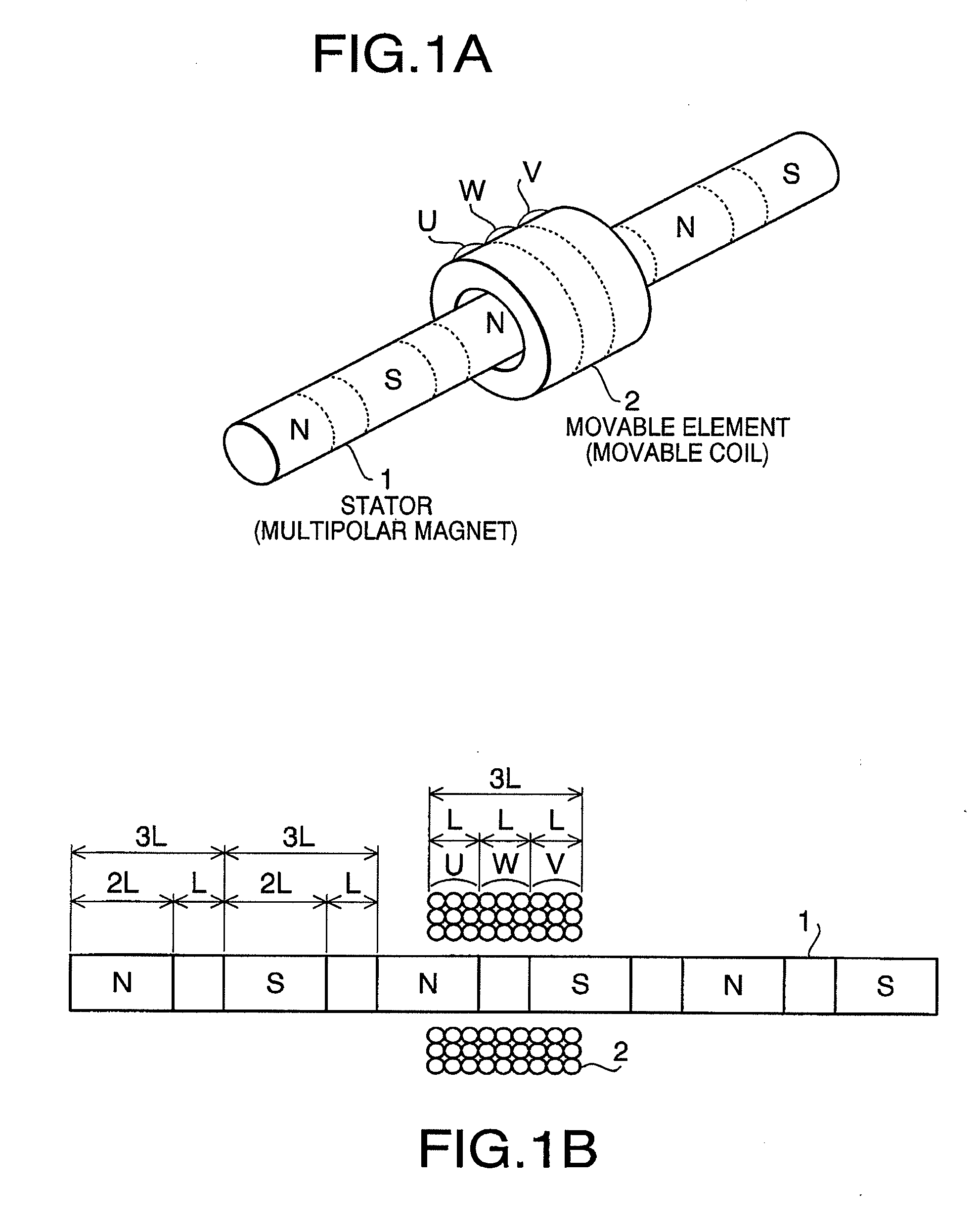
[0026]Hereinafter, referring to accompanying drawings, a first embodiment of the present invention will be described. FIG. 1A and FIG. 1B are a conceptual perspective view and a conceptual configuration diagram of a linear actuator according to the invention, respectively. An example of the linear actuator is illustrated here that a cylindrical rod shaped multipolar magnetized magnet 1 is arranged as a stator, and a movable coil 2 as a coiled body of the present invention is arranged as a movable element to be face to face with periphery around the long axis direction of the multipolar magnetized magnet 1 and to move linearly along the length direction of the multipolar magnetized magnet 1.

[0027]The multipolar magnetized magnet 1 is formed to be a cylindrical rod shaped isotropic magnet material having a necessary diameter size and length, and is magnetized into S-poles and N-poles alternately at a regular interval along the axis line of the rod, that is, axial direction thereof. Wh...

second embodiment

[0037]FIG. 5A is a conceptual configuration diagram of a linear actuator according to a second embodiment. Configuration of a multipolar magnetized magnet 1 as a multipolar magnet is the same as that in the first embodiment. As for a movable coil 2A as a coiled body of the present invention, two three-phase coils, each of which is similar to the three-phase coil in the first embodiment, are connected along the axial direction to form the movable coil 2A. Although the respective length along the axial direction and the number of winding turns of the respective three coils of u coil, w coil, and v coil forming the three-phase coil are the same as those of the first embodiment, here in the six coils forming the two three-phase coils, two u coils (u1 coil and u2 coil), two v coils (v1 coil and v2 coil), and two w coils (w1 coil and w2 coil) are arranged side by side along the axial direction. That is, the six coils are arranged in the order of u1 coil, w1 coil, v1 coil, u2 coil, w2 coil...

third embodiment

[0041]FIG. 6A is a conceptual configuration diagram of a linear actuator according to a third embodiment. Configuration of a multipolar magnetized magnet 1 as a multipolar magnet is the same as that in the first embodiment. As for a movable coil 2B, nine coils forming the movable coil 2B are configured that three three-phase coils are connected along the axial direction. Although the respective length along the axial direction and the number of winding turns of the respective three coils of u coil, w coil, and v coil forming the three-phase coil are the same as those of the first embodiment, here in the respective u coils (u1 coil, u2 coil, and u3 coil), v coils (v1 coil, v2 coil, and v3 coil), and w coils (w1 coil, w2 coil, and w3 coil) of the three three-phase coils: u1, u2, and u3 coils; w1, w2, and w3 coils; and v1, v2, and v3 coils; are arranged in the same order along the axial direction. That is, the coils are arranged in the order of u1 coil, w1 coil, v1 coil, u2 coil, w2 co...


PUM


Abstract

There is provided a linear actuator, which is provided with a multipolar magnet arranged with a plurality of S-poles and N-poles alternately along an axial direction thereof; and a coiled body arranged to be relatively movable in the axial direction face to face with respect to the multipolar magnet. In this configuration, the multipolar magnet comprises an integrally formed isotropic magnet material which is magnetized into S-poles and N-poles alternately along the axial direction thereof.

Description

BACKGROUND OF THE INVENTION[0001]The present invention relates to a linear actuator arranged with a magnet and a coil to be capable of linear movement utilizing magnetic force.[0002]Linear actuator is also referred to as linear type motor (linear motor), and is configured to move either of a magnet or a coil utilizing magnetic force which is generated by energizing a coil arranged in a magnetic field generated by a magnet. For example, a linear actuator which is configured that a plurality of permanent magnets are arranged in series face to face with the same polarity each other so as to form a movable element being alternately arranged with S-poles and N-poles, and a coil as a stator is arranged in a magnetic field region generated by the permanent magnets located outer periphery of the movable element, is proposed in Japanese Patent Provisional Publication No. 2007-282475A (hereafter, referred to as JP 2007-282475A). That is, by controlling direction of electric currents to be app...

Claims


Application Information

Patent Timeline
IPC IPC(8): H02K41/03G02B7/09
CPCH02K41/03G02B7/102
Inventor KUROSAWA, YUICHI
Owner HOYA CORP
Why Eureka
Try Eureka