Led driving topology, light source moudle based thereon, and digital camera having the same

a driving topology and led technology, applied in the direction of process and machine control, instruments, television systems, etc., can solve the problems of increased cost and circuit volume, disadvantageous use of additional boost circuits, and limited serial connection of led arrays that can be driven

Inactive Publication Date: 2009-08-06
RICHTEK TECH
View PDF10 Cites 28 Cited by
  • Summary
  • Abstract
  • Description
  • Claims
  • Application Information

AI Technical Summary

Benefits of technology

[0009]Now that a digital camera is already equipped with a power supply to provide a negative voltage for the light sensor thereof, such as a charge-coupled device (CCD), the aforesaid light source module, when applied to a digital camera, can generate a great voltage difference across the LED array without requiring an additional boost circuit or a high voltage.

Problems solved by technology

However, in some applications, particularly for portable or handheld devices, the number of serially connected LEDs in a LED array that can be driven is limited by the power source voltage provided by the power supplies of such devices.
In order to provide higher voltage than the power source voltage for the LED driver, an additional boost circuit is required, and yet the use of the additional boost circuit is disadvantageous because of the increased cost and circuit volume.
Moreover, as the driving voltage to be used becomes higher, it is necessary for the LED driver to have a circuit made by a high-voltage manufacturing process, which not only results in further increased cost and chip size, but also prevents the circuit from integration into low-voltage chips.

Method used


Image

  • Led driving topology, light source moudle based thereon, and digital camera having the same
  • Led driving topology, light source moudle based thereon, and digital camera having the same
  • Led driving topology, light source moudle based thereon, and digital camera having the same

Examples


Embodiment Construction

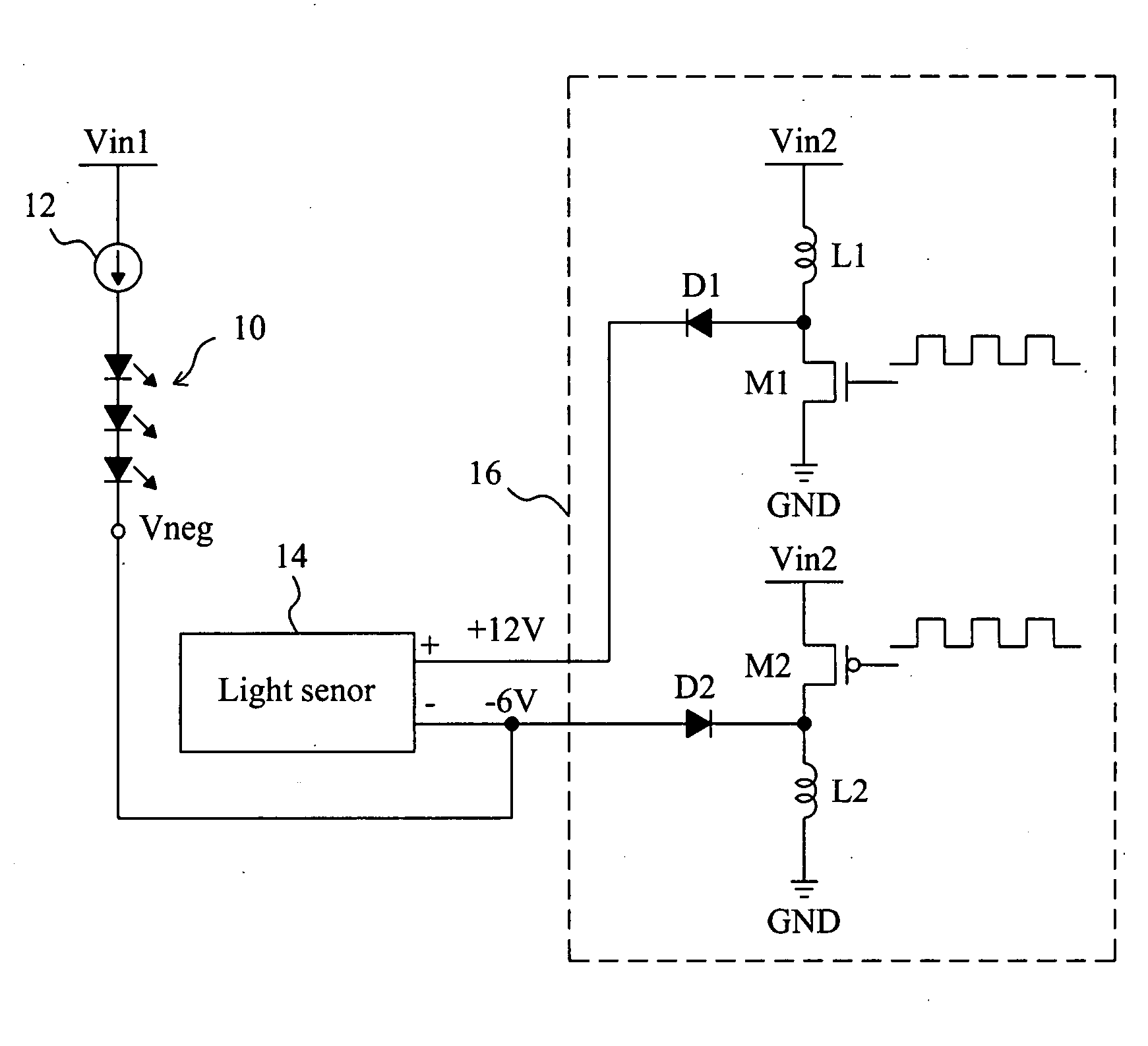
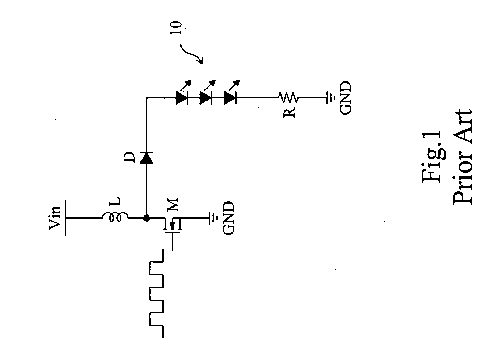
[0015]The turn-on voltage of a LED is the voltage difference across the LED, rather than the absolute voltage at any single end thereof. In the conventional LED driving topology, as the low-voltage end of the LED array is grounded, the abovementioned limitation on applications ensues. According to the present invention, a novel LED driving topology is proposed, in which the low-voltage end of the LED array is applied with a negative voltage to overcome the abovementioned limitation.

[0016]Taking a digital camera for example, FIG. 3 shows a LED light source module designed therefor. A general digital camera includes a light sensor 14, such as a CCD, that needs a positive voltage and a negative voltage for operation. For the positive voltage / negative voltage, typical specifications include +12V / −6V, +14V / −7V and +16V / −8V, and the specification +12V / −6V is exemplified in this embodiment. With the already equipped power supply 16 of the digital camera, the power source voltage Vin2 is co...


PUM


Abstract

A LED driving topology includes a LED array and a current source connected in series between two power inputs receiving a positive voltage and a negative voltage respectively. This topology increases the voltage difference across the LED array and hence has the capability of lighting up more serially connected LEDs, without requiring an additional boost circuit or a high voltage. In addition, the circuit of the current source can be made by a low-voltage manufacturing process.

Description

FIELD OF THE INVENTION[0001]The present invention is related generally to a LED driving topology and, more particularity, to a LED light source module for a digital camera.BACKGROUND OF THE INVENTION[0002]To turn on a light-emitting diode (LED), the voltage difference across the LED must exceed the cutoff voltage thereof. Nowadays, LED applications typically involve configuring a string of LEDs as a LED array, and in consequence a relatively high voltage is needed to drive the LED array. However, in some applications, particularly for portable or handheld devices, the number of serially connected LEDs in a LED array that can be driven is limited by the power source voltage provided by the power supplies of such devices. In order to provide higher voltage than the power source voltage for the LED driver, an additional boost circuit is required, and yet the use of the additional boost circuit is disadvantageous because of the increased cost and circuit volume. Moreover, as the driving...

Claims


Application Information

Patent Timeline
Patent Type & Authority Applications(United States)
IPC IPC(8): H05B41/36H04N5/225H04N5/335H04N5/372
CPCH04N5/2256Y02B20/347H05B33/0815Y02B20/30H05B45/38H05B45/375H04N23/56
Inventor CHEN, CHUNG-TSUNGCHANG, CHUNG-HSIUNGWU, TSAN-HUEICHEN, SHIH-HUI
Owner RICHTEK TECH
Why Eureka
Try Eureka