Optical scanning device and image forming apparatus

a scanning device and image forming technology, applied in the field of optical scanning devices and image forming apparatus, can solve the problems of difficult enhancing scanning accuracy at low cost using optical scanning devices, and the risk of changing the diameter of a light spot on the surface to be scanned from a change in the operating environmen

Active Publication Date: 2009-08-06
RICOH KK
View PDF33 Cites 24 Cited by
  • Summary
  • Abstract
  • Description
  • Claims
  • Application Information

AI Technical Summary

Benefits of technology

[0008]It is an object of the present invention to at lea...

Problems solved by technology

However, because plastic exhibits a greater change in optical characteristics due to moisture absorption or temperature change than glass, there is a risk of changing the diameter of a light spot on the surface to be scanned from a change in the operating environment.
Unfortunately, the optical s...

Method used


Image

  • Optical scanning device and image forming apparatus
  • Optical scanning device and image forming apparatus
  • Optical scanning device and image forming apparatus

Examples


Embodiment Construction

[0037]Exemplary embodiments of the present invention are explained in detail below with reference to the accompanying drawings.

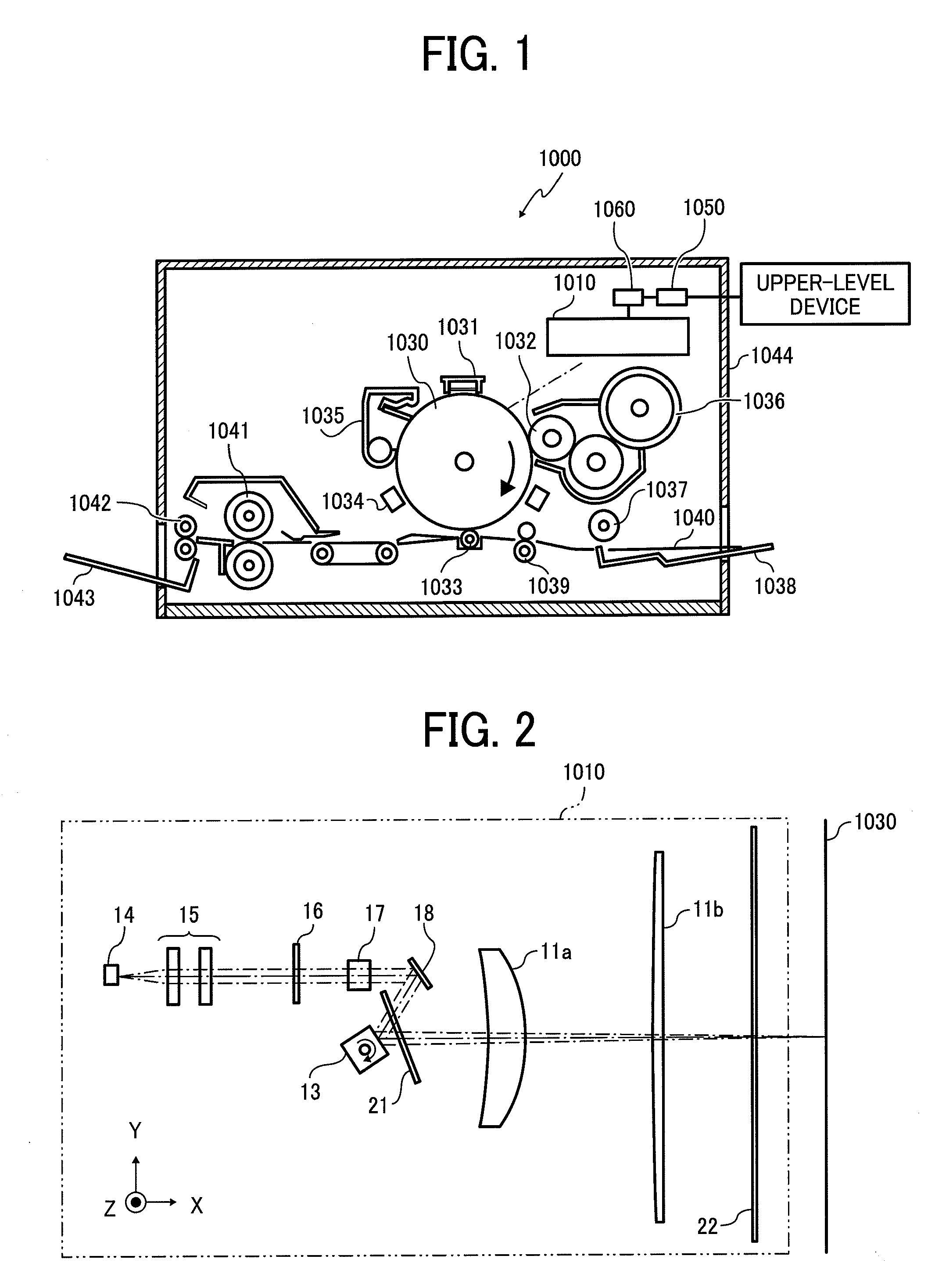
[0038]FIG. 1 is a schematic diagram of a laser printer 1000 as an image forming apparatus according to the present invention.

[0039]The laser printer 1000 includes an optical scanning device 1010 according to a first embodiment of the present invention, a photosensitive drum 1030, a charging unit 1031, a developing roller 1032, a transfer charging unit 1033, a neutralizing unit 1034, a cleaning unit 1035, a toner cartridge 1036, a feed roller 1037, a feed tray 1038, a pair of registration rollers 1039, a fixing roller 1041, a discharge roller 1042, a discharge tray 1043, a communication control unit 1050, a printer control unit 1060 that controls each of the components, and so forth. These components are arranged at predetermined positions in a printer casing 1044.

[0040]The communication control unit 1050 controls a bi-directional communication with an upper-...


PUM


Abstract

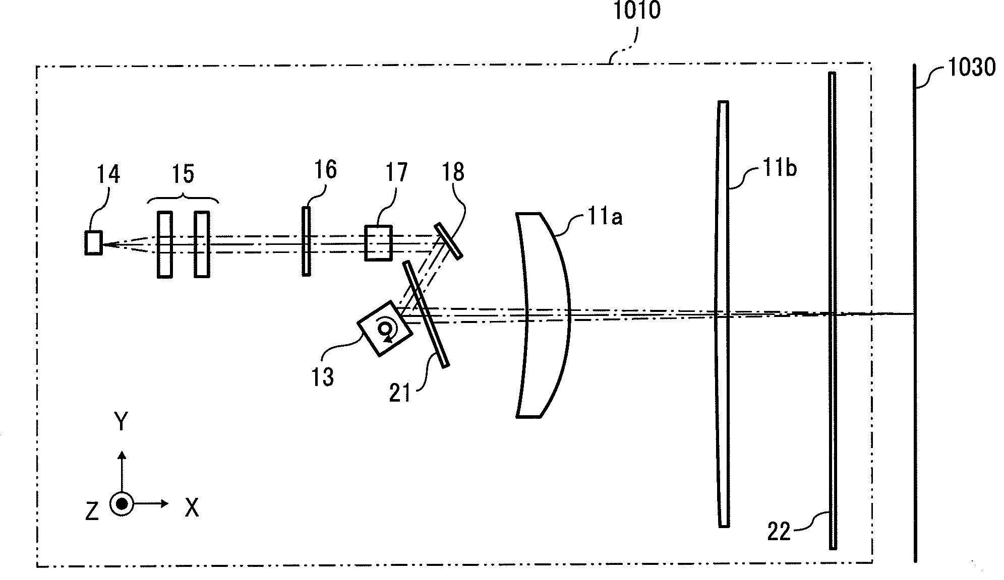
A first optical system couples a light beam from a light source, including a first lens made of glass with a positive power and a second lens made of plastic with a negative power. A second optical system focuses the light beam from the first optical system onto a scanning surface and moves a light spot on the scanning surface in a main-scanning direction. One of an incidence plane and an output plane of the first lens is spherical while the other is spherical or flat. A cross-sectional plane of the second lens along one of the main-scanning direction and a sub-scanning direction has a non-arc shape on at least one of the incidence plane and the output plane.

Description

CROSS-REFERENCE TO RELATED APPLICATIONS[0001]The present application claims priority to and incorporates by reference the entire contents of Japanese priority document 2008-024681 filed in Japan on Feb. 5, 2008.BACKGROUND OF THE INVENTION[0002]1. Field of the Invention[0003]The present invention relates to a technology for scanning a target surface with a light beam.[0004]2. Description of the Related Art[0005]In recent years, there has been a growing demand for low-cost image forming apparatuses such as laser printers and digital copiers. One approach for achieving such low-cost image forming apparatuses is to employ scanning lenses made of plastic in an optical scanning device. However, because plastic exhibits a greater change in optical characteristics due to moisture absorption or temperature change than glass, there is a risk of changing the diameter of a light spot on the surface to be scanned from a change in the operating environment.[0006]To overcome this problem, optical ...

Claims


Application Information

Patent Timeline
IPC IPC(8): G02B26/10
CPCG02B26/124
Inventor ICHII, DAISUKEHIRAKAWA, MAKOTO
Owner RICOH KK
Why Eureka
Try Eureka