Wireless programmable logic device

a programmable logic and logic device technology, applied in the field of computing devices, can solve the problems of heat generation, reduced capabilities, and increased complexity of the basic architecture of the programmable logic device, and reduce the capacity and size of the devi

Inactive Publication Date: 2009-08-06
AVAGO TECH WIRELESS IP SINGAPORE PTE
View PDF99 Cites 6 Cited by
  • Summary
  • Abstract
  • Description
  • Claims
  • Application Information

AI Technical Summary

Problems solved by technology

As integrated circuit technology advances, the basic architecture of a programmable logic device is increasing in complexity, capabilities, and size reduction.
As is known, the transferring of data via the traces and drivers consumes a significant amount of power, which produces heat.
With many programmable logic devices architectures, heat dissipation is a critical issue.
In addition, the numerous traces within the programmable logic device to support the switching function of the switching modules exhibits various transmission line and / or line propagation issues, which limits size reduction, frequency of operation, and / or performance.

Method used


Image

  • Wireless programmable logic device
  • Wireless programmable logic device
  • Wireless programmable logic device

Examples


Embodiment Construction

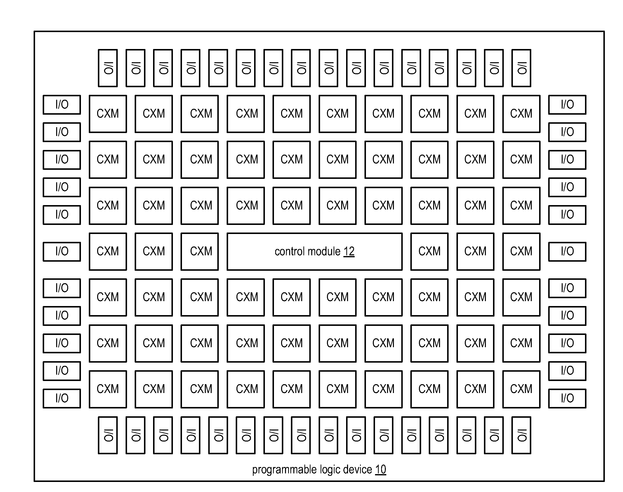
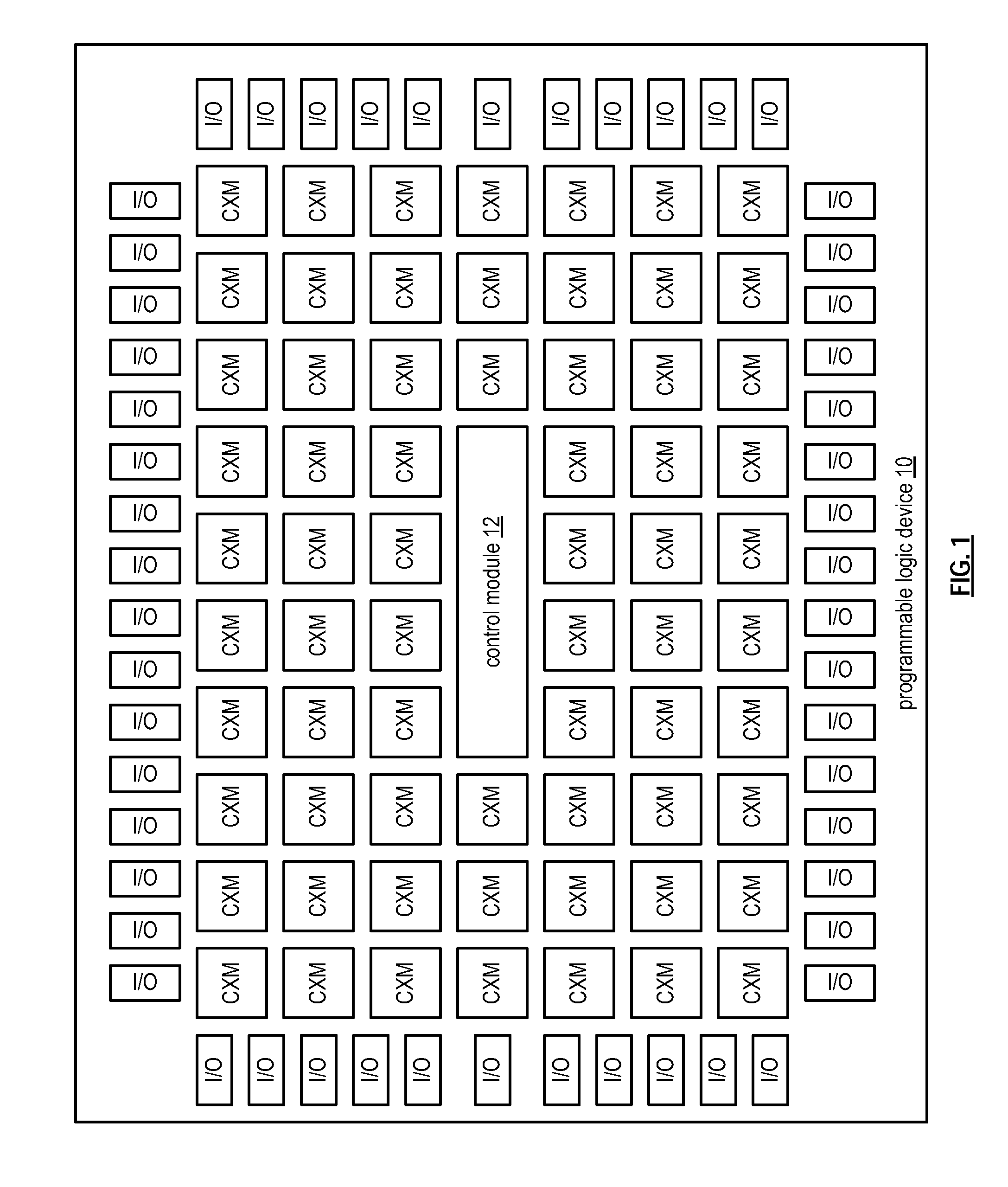
[0038]FIG. 1 is a schematic block diagram of an embodiment of a programmable logic device 10 that includes a control module 12, a plurality of a plurality of input / output (I / O) modules, and a plurality of configurable logic and millimeter wave (MMW) transceiver modules (CXM). Each of the I / O modules includes one or more I / O blocks and a MMW transceiver and each of the CXMs includes one or more configurable logic blocks (CLB) and a MMW transceiver.

[0039]The control module 12 (an embodiment of which will be described in greater detail with reference to FIG. 8) functions to receive a programming instruction. The programming instruction may be one of a plurality of programming instructions to configure the programmable logic device 10. The plurality of programming instructions may be generated from a netlist, which in turn may be generated from a program written in a hardware description language or from a schematic design.

[0040]The control module 12 then identifies a set of the plurali...


PUM


Abstract

A programmable logic device includes a control module, a plurality of input/output modules, and a plurality of configurable logic and millimeter wave (MMW) transceiver modules (CXM). The control module is operable to: receive a programming instruction; identify a set of the plurality of CXMs based on the programming instruction; identify at least one of the plurality of input/output modules based on the programming instruction; determine configuration of the set of the plurality of CXMs and the at least one of input/output modules in accordance with the programming instruction; and allocate wireless communication resources of the programmable logic device to support the configuration of the set of the plurality of CXMs and the at least one of the plurality of input/output modules.

Description

[0001]This patent application is claiming priority under 35 USC §120 as a continuation in part patent application of co-pending patent applications:[0002]1. entitled COMPUTING DEVICE WITH HANDHELD AND EXTENDED COMPUTING UNITS, having a filing date of Feb. 6, 2008, and a Ser. No. 12 / 026,681;[0003]2. RF BUS CONTROLLER, having a filing date of Jan. 31, 2007, and a Ser. No. 11 / 700,285; and[0004]3. entitled FLASH MEMORY WITH MILLIMETER WAVE HOST INTERFACE AND METHOD FOR USE THEREWITH, having a filing date of Jul. 31, 2007, and a Ser. No. 11 / 888,068.STATEMENT REGARDING FEDERALLY SPONSORED RESEARCH OR DEVELOPMENT[0005]NOT APPLICABLEINCORPORATION-BY-REFERENCE OF MATERIAL SUBMITTED ON A COMPACT DISC [0006]NOT APPLICABLEBACKGROUND OF THE INVENTION[0007]1. Technical field of the Invention[0008]This invention relates generally to computing devices and more particularly to components of such computing devices.[0009]2. Description of Related Art[0010]Communication systems are known to support wir...

Claims


Application Information

Patent Timeline
Patent Type & Authority Applications(United States)
IPC IPC(8): H04L12/28
CPCH03K19/17744H03K19/17756H03K19/17752
Inventor MARKISON, TIMOTHY W.
Owner AVAGO TECH WIRELESS IP SINGAPORE PTE
Why Eureka
Try Eureka