Lattice-reduction-aided MIMO detectors

a technology of lattice base reduction and detector, applied in the field of wireless communication systems, can solve the problems of affecting the quality and efficiency of such approaches, the process of finding a good lattice base reduction can be significantly complicated, and the signal detection and decoding is more complex in the mimo network, so as to reduce complexity and time, and accurately detect the transmitted symbols

Inactive Publication Date: 2009-08-06
HUI LONG FUND LIABILITY
View PDF2 Cites 11 Cited by
  • Summary
  • Abstract
  • Description
  • Claims
  • Application Information

AI Technical Summary

Benefits of technology

[0009]Since LLL lattice reduction is an iterative algorithm, the LLL can be stopped before continuing to another iteration when predetermined conditions occur. For example, the LLL can be stopped if a predetermined number of vectors have been swapped or the processing time has exceeded some predetermined threshold. Although stopping early prevents an ultimate reduced lattice solution from being determined, it can reduce complexity and the time needed to accurately detect the transmitted symbols.

Problems solved by technology

However, signal detection and decoding is more complex in MIMO networks than in conventional wireless networks that have only a single receive / transmit antenna per attached device.
Further, the relative degree of freedom provided by such lattice-based approaches in choosing a lattice basis can be a significant factor affecting the quality and efficiency of such approaches.
However, the process of finding a good lattice basis reduction can be significantly complicated in many conventional lattice-based signal detection approaches as compared to other components of such approaches, such that the lattice reduction complexity of conventional lattice-based signal detection techniques often dominates the overall detection complexity.
Moreover, this disparity in complexity generally becomes more significant as the dimension of the associated communication system increases.
As a result, difficulties arise in applying conventional signal detection techniques in many communication systems, such as those where an associated channel matrix or related lattice basis undergo frequent changes.
Other problems with the state of the art may become further apparent upon review of the description of various non-limiting embodiments that follows.

Method used


Image

  • Lattice-reduction-aided MIMO detectors
  • Lattice-reduction-aided MIMO detectors
  • Lattice-reduction-aided MIMO detectors

Examples


Embodiment Construction

[0023]The present invention is now described with reference to the drawings, wherein like reference numerals are used to refer to like elements throughout. In the following description, for purposes of explanation, numerous specific details are set forth in order to provide a thorough understanding of the present invention. It may be evident, however, that the present invention may be practiced without these specific details. In other instances, well-known structures and devices are shown in block diagram form in order to facilitate describing the present invention.

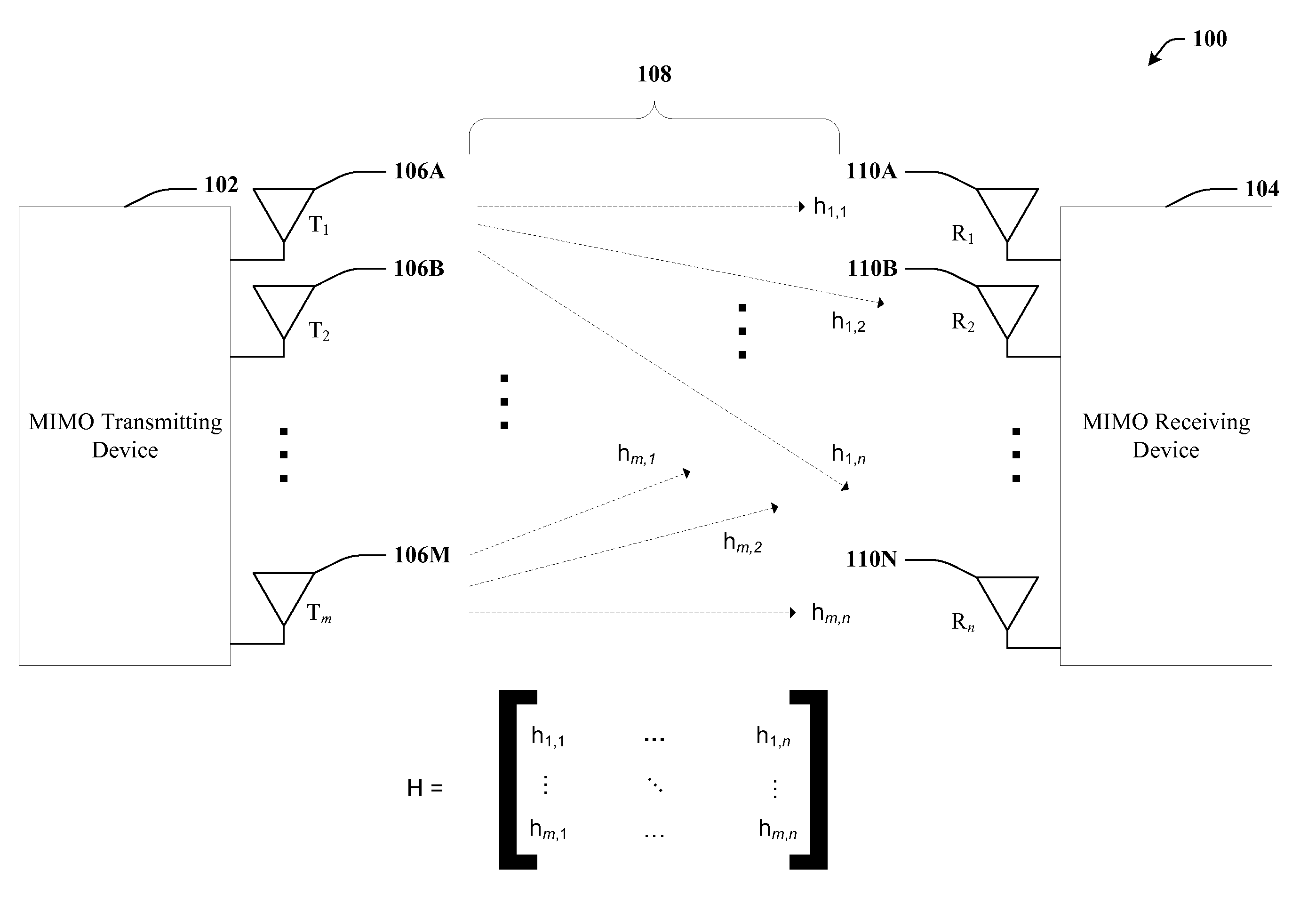
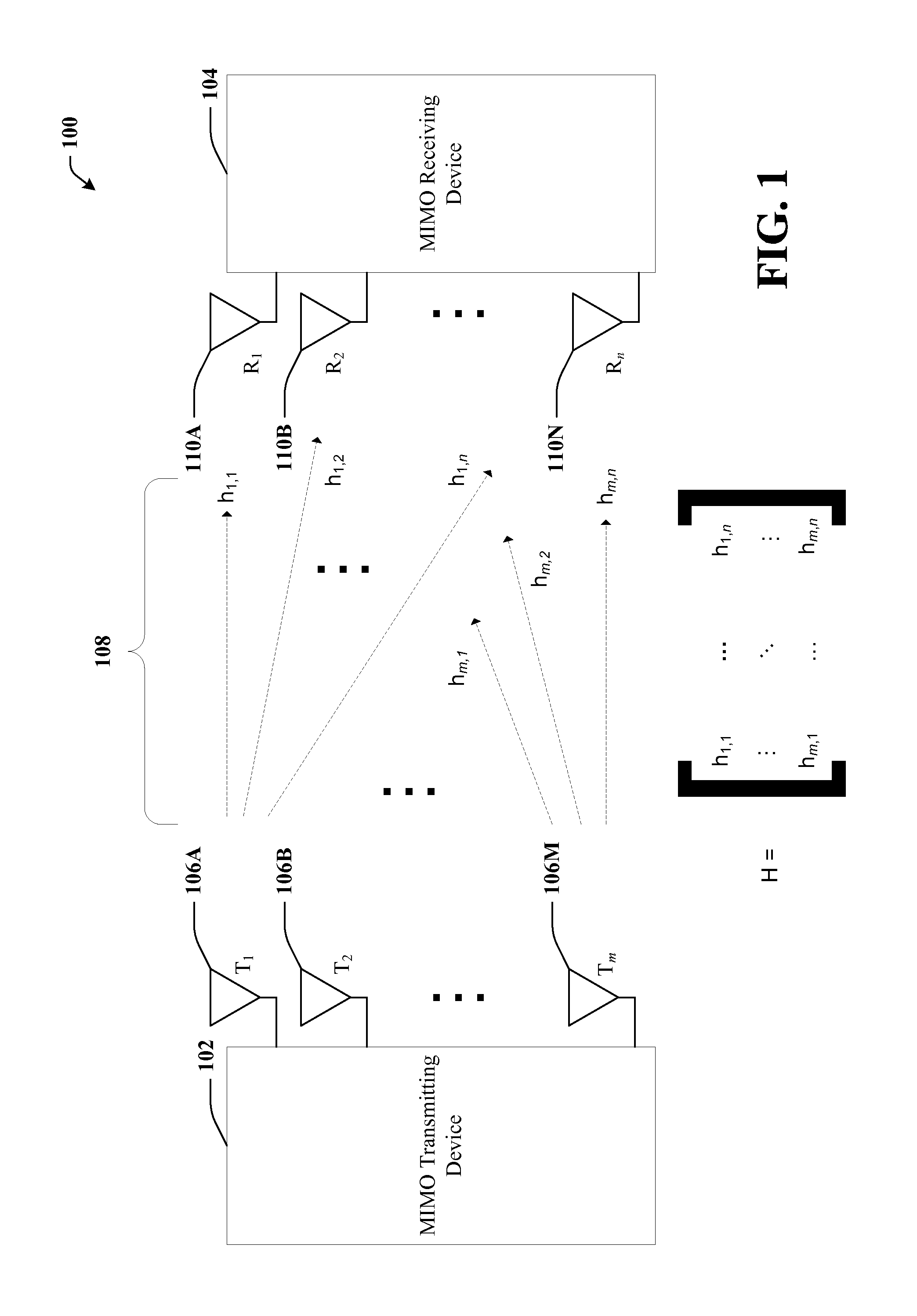
[0024]Turning to FIG. 1, an exemplary operating environment 100 is illustrated. In particular, a MIMO transmitting device 102 and a MIMO receiving device 104 are illustrated. The MIMO transmitting device 102 has m transmitting antennas (106A, 106B . . . 106M). Each transmitting antenna send data over channel 108 to n receiving antennas. For the sake of clarity, it is assumed that m104 and a MIMO transmitter 102.

[0025]FIG....


PUM


Abstract

A Lenstra-Lenstra-Lovász (LLL)-based technique is utilized to reduce the complexity of a MIMO detector. Basis vectors can be pre-sorted, such as by V-BLAST ordering or sorted-QR ordering, prior to applying Gram-Schmidt Orthogonalization (GSO) to further improve performance. Alternatively, a joint sorting and LLL reduction (JSAR) technique can be utilized such that after each reduction step, a vector remaining to be reduced can be selected that will minimize the overall complexity. The JSAR technique can be applied on real or complex lattice bases. LLL reduction can be stopped after a predetermined threshold is exceeded.

Description

TECHNICAL FIELD[0001]The subject disclosure relates generally to wireless communications systems, and more particularly to signal detection in multiple-input multiple-output (MIMO) systems.BACKGROUND OF THE INVENTION[0002]Wireless communication networks are increasingly popular and widely deployed. Multiple-input multiple-output (MIMO) technology is a promising candidate for next-generation wireless communications. However, signal detection and decoding is more complex in MIMO networks than in conventional wireless networks that have only a single receive / transmit antenna per attached device.[0003]The linearity of a communication channel and the lattice structure of a modulation scheme can be exploited to state many signal detection problems as a problem of finding a nearest lattice point. Further, the relative degree of freedom provided by such lattice-based approaches in choosing a lattice basis can be a significant factor affecting the quality and efficiency of such approaches. F...

Claims


Application Information

Patent Timeline
Patent Type & Authority Applications(United States)
IPC IPC(8): H04L27/28
CPCH04L25/0204H04L2025/03643H04L2025/03426H04L25/0248
Inventor GAN, YING HUNGMOW, WAI HO
Owner HUI LONG FUND LIABILITY
Why Eureka
Try Eureka