Blade support limb for vertical axis wind turbine
a support limb technology, which is applied in the direction of wind rotors, greenhouse gas reduction, vessel construction, etc., can solve the problems of reducing the efficiency of the vertical axis wind turbine, the inability of the wind rotor to operate, and the power will be very low under a low wind speed, so as to achieve constant power
- Summary
- Abstract
- Description
- Claims
- Application Information
AI Technical Summary
Benefits of technology
Problems solved by technology
Method used
Image
Examples
example 1
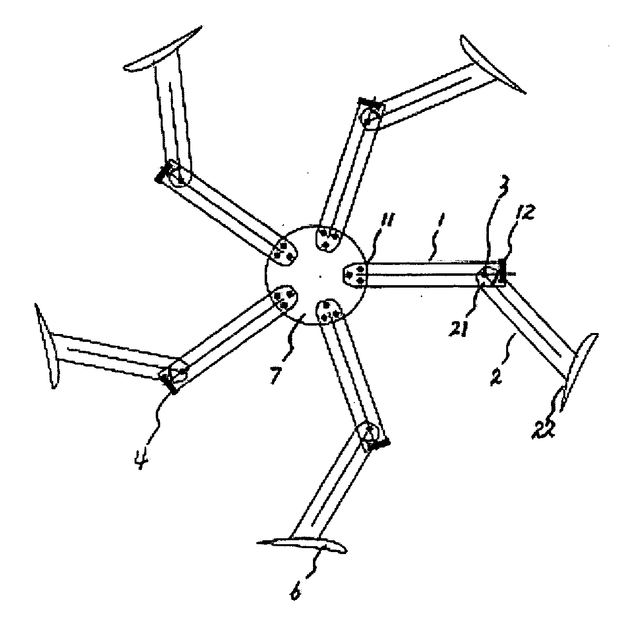
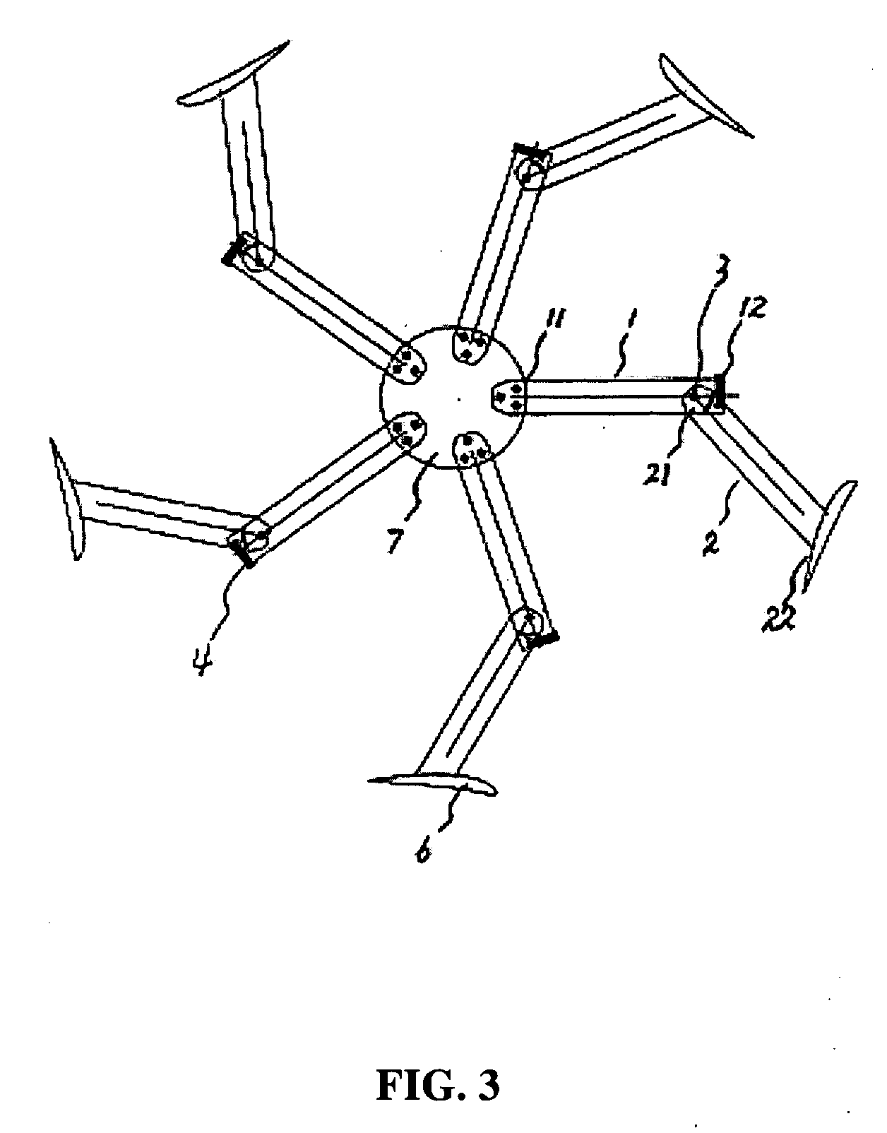
[0039]FIG. 3 is the blade support limb structure of vertical axis wind turbine in this invention. The other end (11) of a fixed support limb (1) is fixed with the flange on the vertical axis. One end (21) of a rotatable support limb (2) is connected with one end (12) of the fixed support limb, and may rotate around one end (12) of the fixed support limb. The other end (22) of the rotatable support limb is fixed with blades. There is a gyration center axis (3) at the connection of one end (21) of the rotatable support limb and one end (12) of the fixed support limb, and the rotatable support limb may rotate around it. There is a control component (4) at one end (12) of the fixed support limb, which is used to control the rotation angle (β) of the rotatable support limb (2) around the gyration center axis (3). Both ends (41) (42) of the control component respectively control one end (21) of the rotatable support limb and one end (12) of the fixed support limb and control the rotation ...
example 2
[0042]For the blade support limb structure in Implementation Example 1, it is set as the prerequisite that the wind rotor with the diameter 1.36 m consists of blades of Goe63 airfoil, the length ratio of fixed support limb and rotatable support limb is 1:1, and the rated wind speed is 10 m / s, i.e. the wind speed of such device begins to affect the vertical axis wind turbine from 10 m / s. Through CFD, when the wind speed increases from 10 m / s to 15 m / s, 20 m / s and 25 m / s, the output power increases respectively from 170 watt to 210 watt, 220 watt and 230 watt. But the output power will increase from 170 watt to about 2660 watt without the blade support limb structure in this invention.
CFD calculation tableWind speed10 m / s15 m / s20 m / s25 m / sPower output by using existing17035013602660blade support limb structure (watt)Power output by using the blade170210225230support limb structure in thisinvention (watt)
example 3
[0043]Also for the blade support limb structure in Implementation Example 1, wind tunnel tests are performed by means of the same wind rotor and parameters. It is set as the prerequisite that the length ratio of fixed support limb and rotatable support limb is 1:1, when the wind speed increases from 10 m / s to 15 m / s, 20 m / s and 25 m / s, the output power of the motor increases respectively from 158 watt to 193 watt, 198 watt and 202 watt. But the output power of the motor will reach about 2600 watt without such device.
Table of wind tunnel testsWind speed10 m / s15 m / s20 m / s25 m / sPower output by using16057013202600existing blade supportlimb structure (watt)Power output by using158193198202the blade support limbstructure in thisinvention (watt)
PUM
 Abstract
Description
Claims
Application Information
 - R&D
- Intellectual Property
- Life Sciences
- Materials
- Tech Scout
- Unparalleled Data Quality
- Higher Quality Content
- 60% Fewer Hallucinations
Browse by: Latest US Patents, China's latest patents, Technical Efficacy Thesaurus, Application Domain, Technology Topic, Popular Technical Reports.
© 2025 PatSnap. All rights reserved.Legal|Privacy policy|Modern Slavery Act Transparency Statement|Sitemap|About US| Contact US: help@patsnap.com


