Method for dewatering and a dewatering apparatus

a technology of dewatering apparatus and mesh, which is applied in the direction of machine wet end, papermaking, textiles and papermaking, etc., can solve the problems of continuous md direction decrease of the water weight of fibrous materials on the mesh, unsatisfactory formation profiles, and unacceptable cd profiles

Inactive Publication Date: 2009-08-13
VOITH PATENT GMBH
View PDF2 Cites 13 Cited by
  • Summary
  • Abstract
  • Description
  • Claims
  • Application Information

AI Technical Summary

Benefits of technology

[0038]The dewatering elements are arranged, in at least one section of the dewatering apparatus. They can be arranged favorably in, or in a region of, a steam blow box or a press or a headbox, in particular a dilution water headbox. In addition, the dewatering performance can be influenced by an adjustable suction force and/or an adjustable layer thickness and/or the preferably adjustable consistency of the fibrous material emerging from the headbox and/or a preferably adjustable pressurization of the fibrous material by an opposing element and a second mesh. Through the adaptation or control of dewatering elements, in particular of different types of dewatering elements, in different sections of the dewatering apparatus i...

Problems solved by technology

In spite of the consistency of the fibrous material being adjusted by dilution water at the dilution water headbox, the problem often arises in the MD direction, but in particular also in the CD direction, of unsatisfactory formation profiles, in particular unacceptable CD profiles, arising for example due to uneven dewatering on the mesh.
After the fibrous material is applied onto the mesh, said material continuously loses water due to gravitation or additional vacuum extraction with the help of dewatering elements, with the result that the water weight of the fibrous material on ...

Method used


Image

  • Method for dewatering and a dewatering apparatus
  • Method for dewatering and a dewatering apparatus
  • Method for dewatering and a dewatering apparatus

Examples


first embodiment

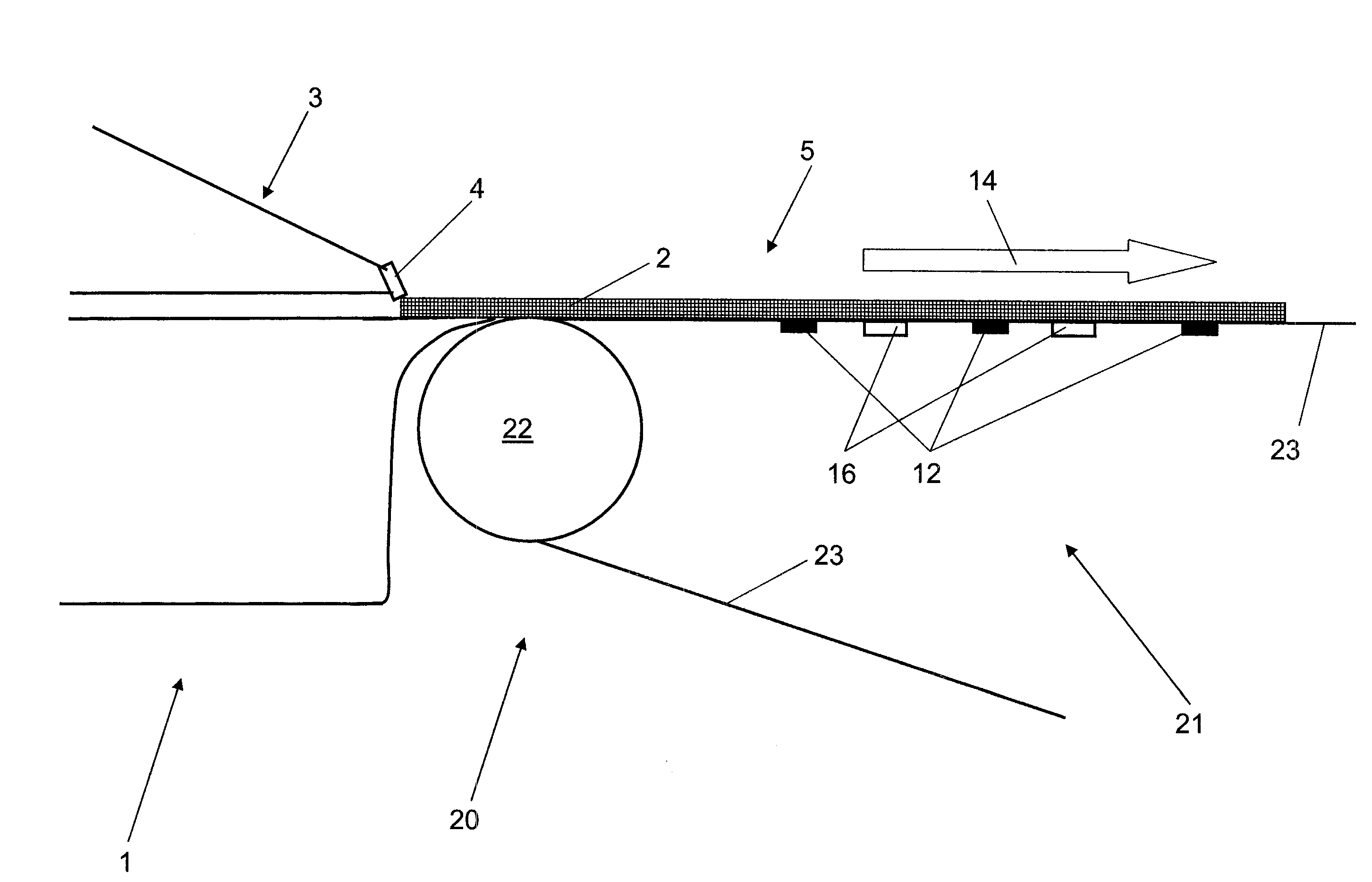
[0050]Referring now to the figures there is described below an inventive dewatering apparatus 1, which in this case is a paper machine or paperboard machine. The paper machine or paperboard machine 1 implements the inventive method.

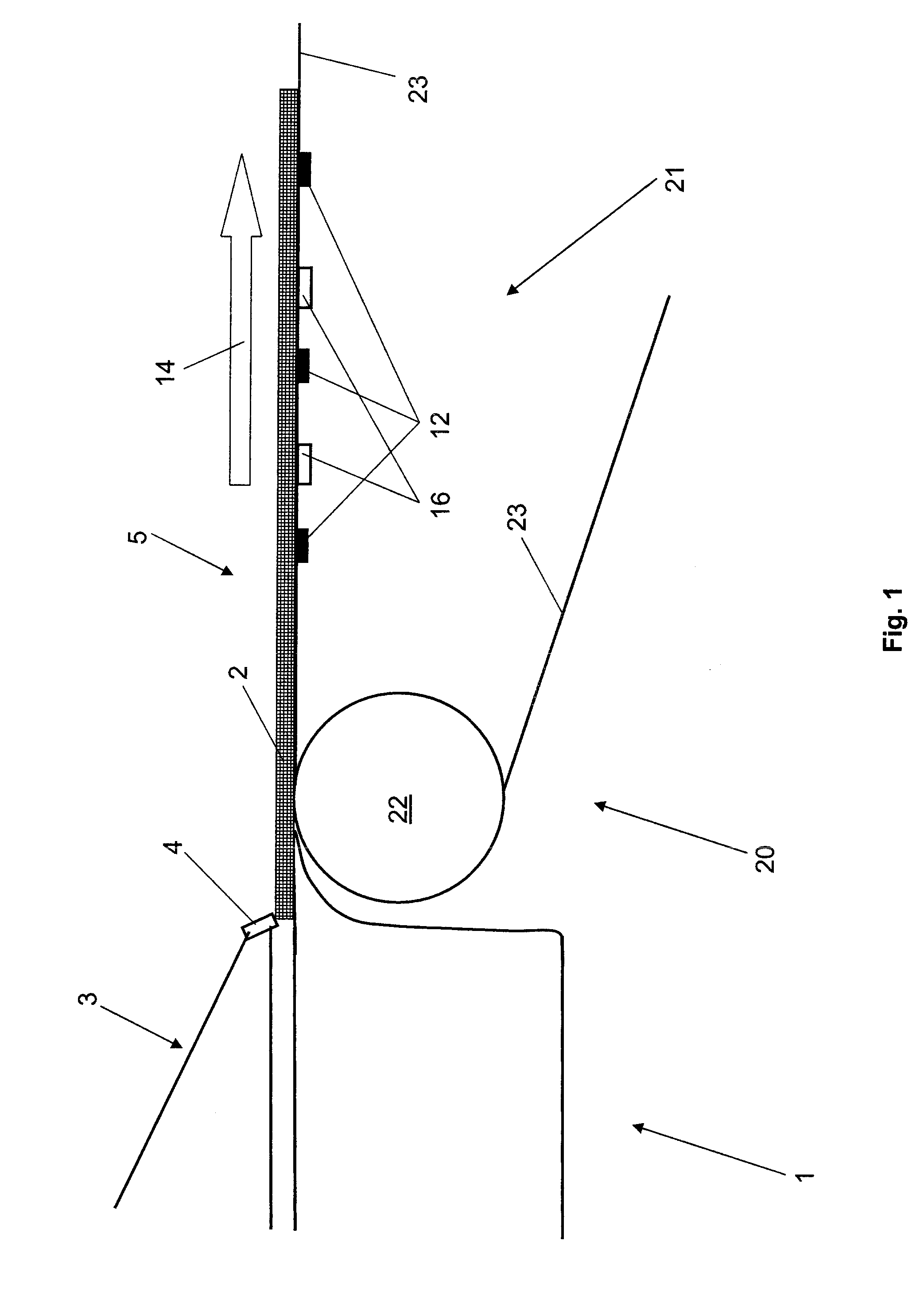
[0051]The paper machine or paperboard machine 1 has a wet section 20 with a dewatering apparatus 21, in which a fibrous material 2 is applied onto a long mesh 23 by a headbox 3. Headbox 3 is constructed as a dilution water headbox. Dilution water headbox 3 has along CD direction 15 of a fibrous web 5 a plurality of fibrous material outlet openings 4.

[0052]With the help of dewatering elements 16 there takes place a first dewatering step for fibrous material 2 in fibrous web 5 conveyed on long mesh 23. Dewatering elements 16 are constructed here as suction boxes 16. The embodiment shown includes two suction boxes 16, whose dewatering performance is zonally adjustable. The paper machine or paperboard machine 1 has further sections such as a drying section, a...

second embodiment

[0063]Inventive features not presented in FIG. 3 are shown in FIG. 4, which presents the present invention.

[0064]Dewatering elements 16 are available in both embodiments only in, or in the region of, wet section 20. However, dewatering elements 16 could also be arranged, in particular respectively in addition or solely, in at least one additional section of dewatering apparatus 1, such as in a steam blower box or in a press or in a headbox 3, in particular in a dilution water headbox 3.

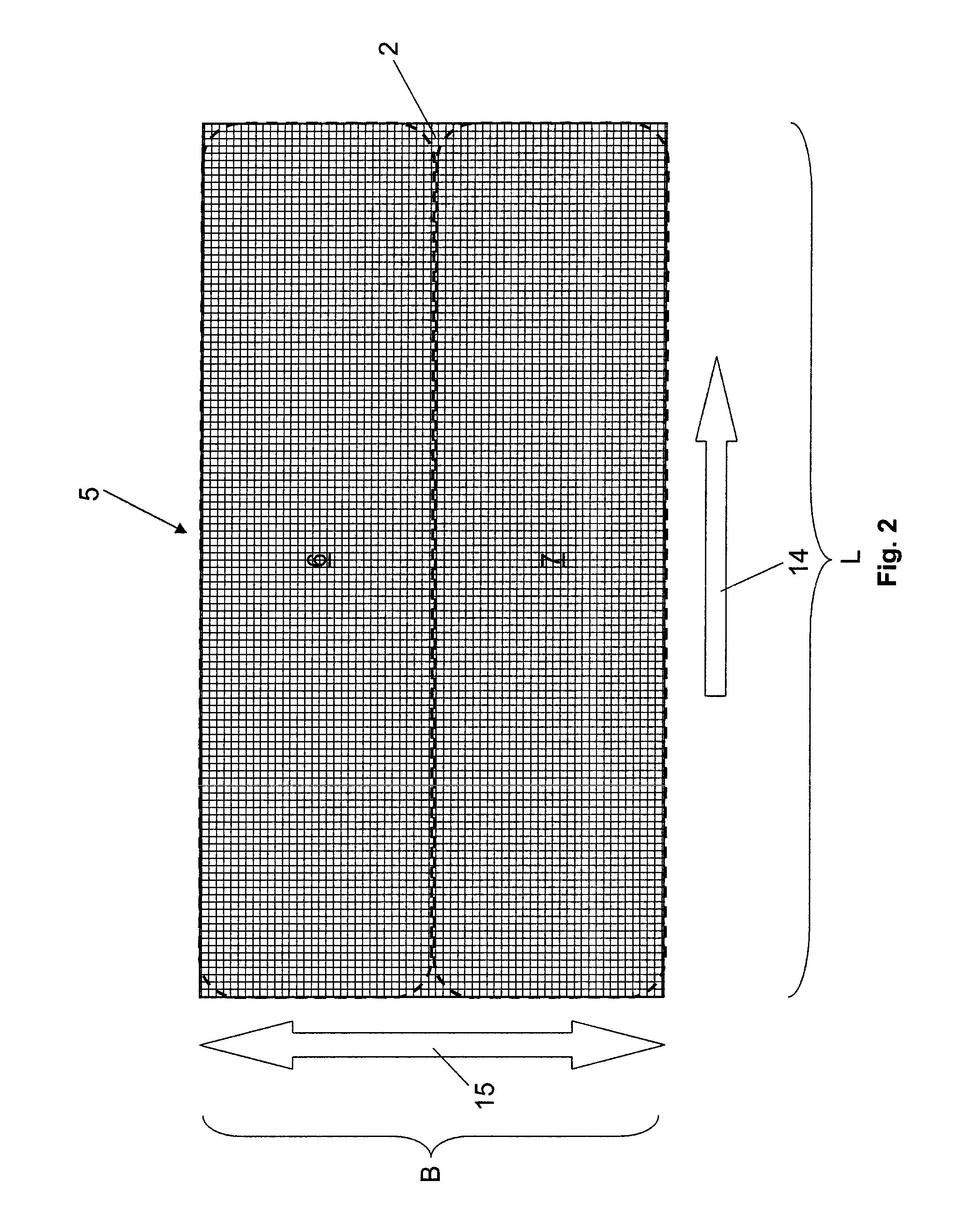
[0065]The first embodiment has three one-dimensional sensor arrangements 13 which are offset in pairs in CD direction 15 and have five water weight sensors 12 each. Sensor arrangements 13 and hence their sensors 12 are also set apart from each other in MD direction 14. The result is therefore a very regular periodicity as a pattern of sensors 12. A different pattern or different periodicity of sensors 12 is implemented on the second embodiment, which is presented in FIG. 4.

[0066]On the second embodime...


PUM


Abstract

This invention relates to a dewatering apparatus, in particular a paper machine or a paperboard machine, for the adjustable, and controllable dewatering of a fibrous material, which is conveyed as a fibrous web that can be divided into at least two zones arranged side by side in a cross direction (CD). The dewatering apparatus is characterized in that the dewatering of the fibrous material is adaptable to a dewatering curve defined in a machine direction on the basis of measurements of the water weight of the fibrous material taken by at least two water weight sensors, in particular a one-dimensional or multi-dimensional sensor arrangement of water weight sensors, which are assigned to a zone and arranged preferably in pairs in mutually offset position in the CD direction.

Description

BACKGROUND OF THE INVENTION[0001]1. Field of the Invention[0002]This invention relates to a dewatering apparatus, for a paper machine or a paperboard machine, for the adjustable, in particular controllable dewatering of a fibrous material which is conveyed as a fibrous web.[0003]2. Description of the Related Art[0004]Dewatering apparatuses and methods for adjusting the dewatering of a fibrous material that is conveyed as a fibrous web, in particular on a belt-shaped mesh, are used in particular in the paper industry. On account of the continuous dewatering of the fibrous material in the machine running direction, called MD direction for short, a paper machine or a paperboard machine can be regarded essentially as a dewatering apparatus for the fibrous material. The machine running direction usually designates, as in this publication, the direction in which the fibrous material is moved during the paper production process on the paper machine or paperboard machine.[0005]At the headbo...

Claims


Application Information

Patent Timeline
IPC IPC(8): D21F11/00D21F1/08
CPCD21F7/003D21G9/0036D21G9/0027
Inventor SPINDLER, JORGHARDT, NIELSMUNCH, RUDOLFKAUFMANN, OLIVERHAAG, JENSBAUER, ARMINABEL, HARTMUT
Owner VOITH PATENT GMBH
Why Eureka
Try Eureka