Method of Manufacturing a Pipe Gasket

a manufacturing method and gasket technology, applied in the field of sealing gaskets, can solve the problems of affecting the adhesion of metal to the pipe, the sealing ring will be displaced from the sealing position in the pipe joint, and the sealing ring made entirely of elastically yielding material generally lack the necessary support effect, so as to achieve the effect of improving the adhesion of metal

Inactive Publication Date: 2009-08-13
S & B TECHN PRODS
View PDF13 Cites 17 Cited by
  • Summary
  • Abstract
  • Description
  • Claims
  • Application Information

AI Technical Summary

Benefits of technology

[0012]Another object of the invention is to provide a sealing gasket with an embedded metal band which features improved adhesion of the metal to the rubber of the gasket.

Problems solved by technology

However, a sealing ring which is formed entirely of a material which is sufficiently soft and elastomeric to provide the sealing function has the disadvantage that it is difficult to retain in the desired position in a groove in connection with the joining of sections of pipe.
There is also the risk that such a sealing ring will be displaced from its sealing position in the pipe joint if the difference of the internal or external pressures on either side of the sealing ring are sufficiently great.
However, as has been discussed, such sealing rings made entirely of elastically yielding material generally lack the necessary support effect to avoid being dislodged during field installation procedures and may not be suitable for use as a combined mold element in a Rieber style manufactured process, as described above.
In these cases, axially directed forces can create substantial twisting within the seal ring.
In those designs utilizing external metal reinforcing bands or rings, it is possible that water, sewage waste or other contaminates could corrode the metal surfaces, thereby degrading the metal band, and in some cases even compromising the integrity of the pipe joint In the case of potable water supply systems, the deterioration of the metal band could possibly contaminate the water supply,

Method used


Image

  • Method of Manufacturing a Pipe Gasket
  • Method of Manufacturing a Pipe Gasket
  • Method of Manufacturing a Pipe Gasket

Examples


Embodiment Construction

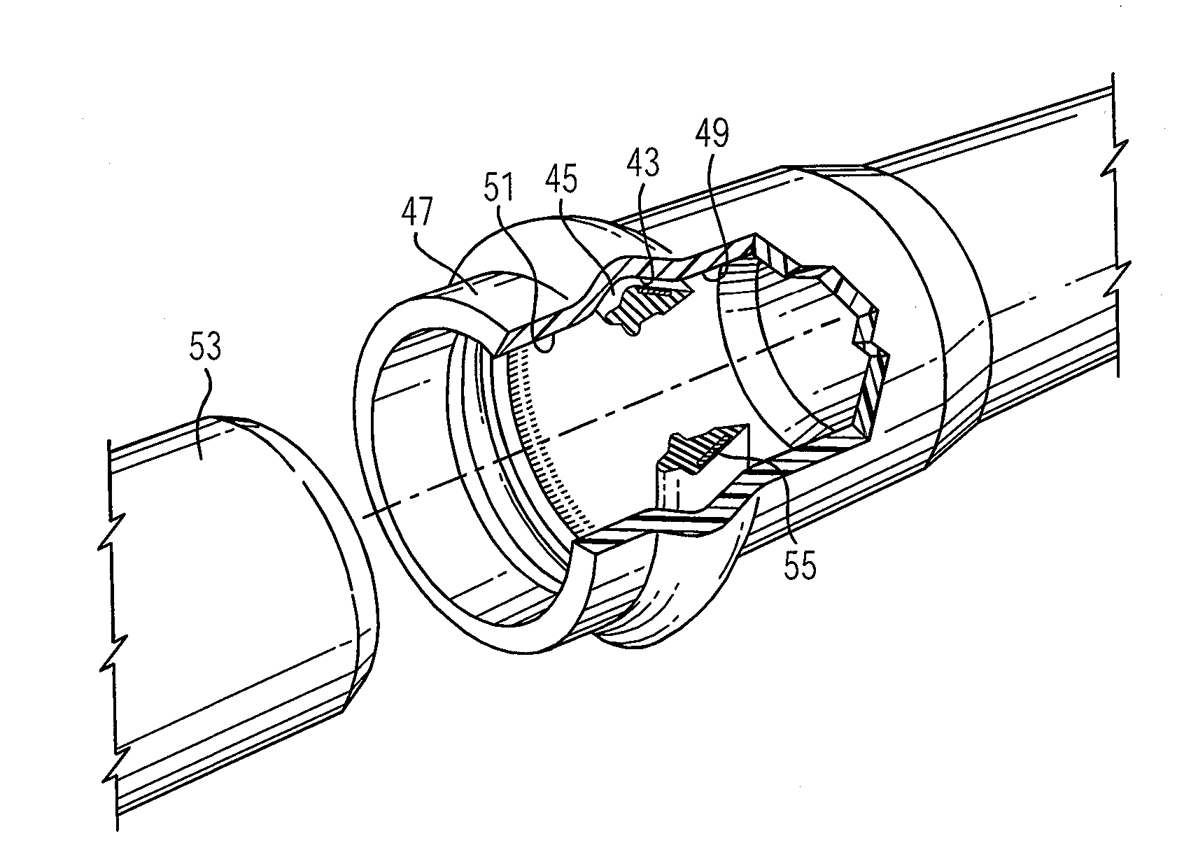
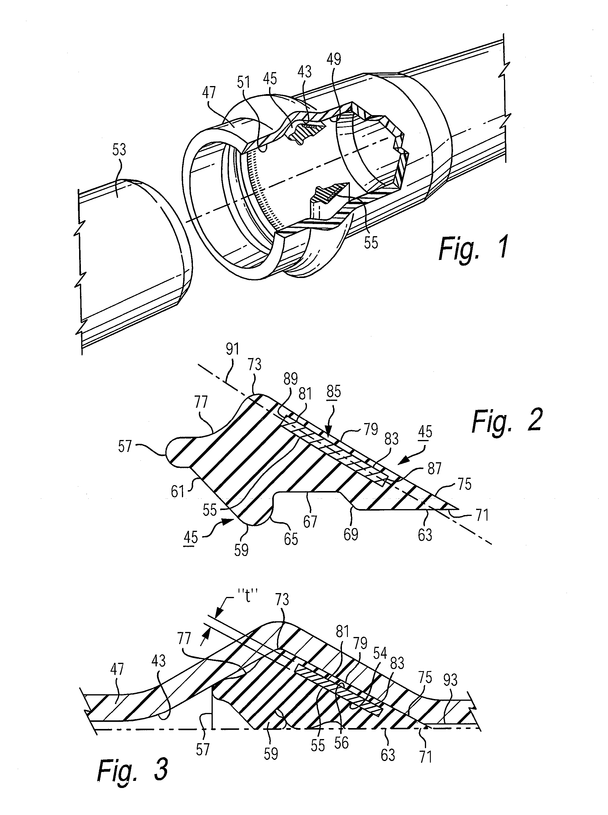
[0027]Turning to FIG. 1 of the drawings, there is shown a sealing gasket of the invention, designated generally as 45 which is installed within a groove 43 provided within the socket end 47 of the illustrated thermoplastic pipe. As shown in FIG. 1, the internal annular groove 43 of the socket end 47 is located between internal cylindrical surfaces 49, 51 of substantially equal diameter. The socket end 47 is intended to be made-up to form a pipe joint with the mating male or spigot pipe section 53 which is inserted within the socket end 47. The sealing gasket 45, as shown in FIG. 1, is disposed within the groove 43 wholly between the cylindrical surfaces concentrically between and sealingly engaging the pipe insert end 53 and the pipe socket end 47 (see FIG. 3) when the joint is made up.

[0028]FIG. 2 shows a typical gasket of the invention in enlarged cross-section for ease of illustration. The gasket 45 is a unitary ring formed of a body of elastically yielding material having a rigi...


PUM

PropertyMeasurementUnit
spacing distanceaaaaaaaaaa
elastomericaaaaaaaaaa
external pressuresaaaaaaaaaa

Abstract

A pipe sealing gasket is shown which is designed to be received within a groove provided within a socket end of a thermoplastic pipe such as PVC pipe used in municipal water and sewer installations. The gasket has a ring shaped body of an elastomeric material and includes a metal reinforcing band. The metal reinforcing band is entirely embedded within the body of elastomeric material during the gasket manufacturing process.

Description

CROSS-REFERENCE TO RELATED APPLICATION[0001]The present application claims priority from earlier filed provisional application Ser. No. 61 / 028,228, filed Feb. 13, 2008, entitled “Method of Manufacturing a Pipe Gasket” by inventor, Herberth Mora.BACKGROUND OF THE INVENTION[0002]1. Field of the Invention:[0003]The present invention relates generally to sealing gaskets used for pipe joints in which a male spigot pipe section is installed within a mating female socket pipe section and to an improved method for manufacturing such sealing gaskets.[0004]2. Description of the Prior Art:[0005]Pipes formed from thermoplastic materials including polyethylene, polypropylene and PVC are used in a variety of industries. For example, such pipes are commonly used in municipal water and sewer applications. In forming a joint between sections of pipe, the spigot or male pipe end is inserted within the female or socket pipe end. An annular, elastomeric ring or gasket is typically seated within a grove...

Claims


Application Information

Patent Timeline
Patent Type & Authority Applications(United States)
IPC IPC(8): B29C45/14
CPCB29C45/14065B29C45/1459B29L2031/265B29K2705/12B29L2023/00B29K2021/00
Inventor MORA, HERBERTH
Owner S & B TECHN PRODS
Why Eureka
Try Eureka