Method for producing metal foil laminate

a metal foil and laminate technology, applied in the direction of layered products, chemistry apparatus and processes, other domestic articles, etc., can solve the problem that metal foil is likely to be peeled off from the insulating base material, and achieve the effect of increasing the tightness of the metal foil lamina

Inactive Publication Date: 2012-01-12
SUMITOMO CHEM CO LTD
View PDF2 Cites 6 Cited by
  • Summary
  • Abstract
  • Description
  • Claims
  • Application Information

AI Technical Summary

Benefits of technology

[0008]Under these circumstances, an object of the present invention is to provide a method for producing a metal foil laminate, which can sufficiently increase tight adhesion of a metal foil laminate even if the metal foil laminate has a large size.
[0009]In order to achieve such an object, the present inventors have found that the ratio of an area of an insulating base material to that of a metal plate is important so as to increase tight adhesion of a metal foil laminate when the insulating base material is sequentially interposed between a pair of metal foils and between a pair of metal plates, followed by heating and pressurizing, and thus the present invention has been completed.
[0011]According to the present invention, since the ratio of an area of an insulating base material to that of a metal plate is limited within a specific range, it becomes possible to sufficiently increase tight adhesion of a metal foil laminate even if the metal foil laminate has a large size.

Problems solved by technology

Therefore, particularly when the metal foil laminate has a large size, tight adhesion of the metal foil laminate is not necessarily sufficiently, and thus the metal foil is likely to be peeled off from the insulating base material in some cases.

Method used


Image

  • Method for producing metal foil laminate
  • Method for producing metal foil laminate
  • Method for producing metal foil laminate

Examples


first embodiment

of the Invention

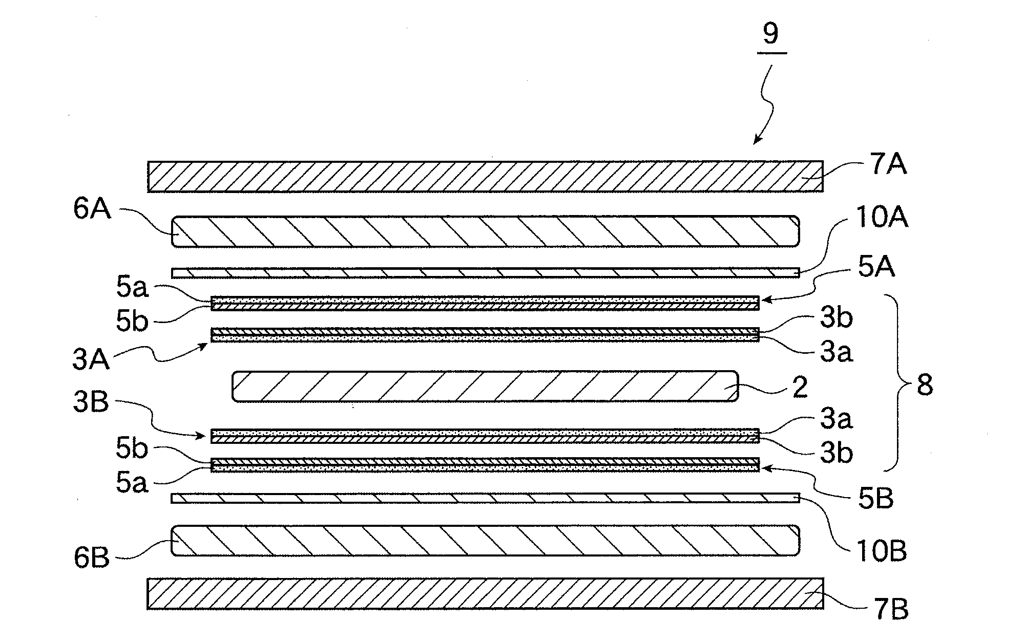
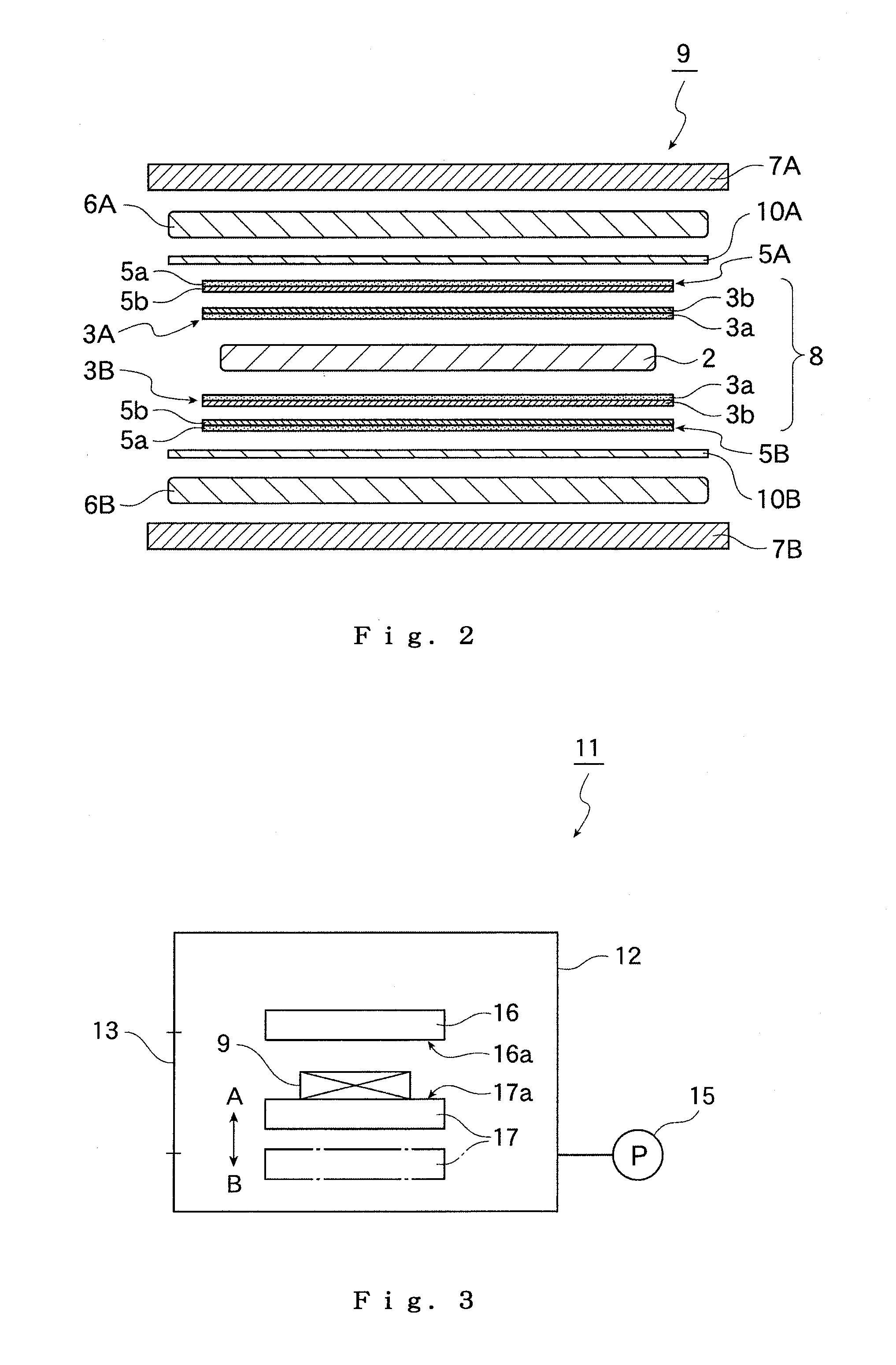
[0017]In FIG. 1 to FIG. 3, First Embodiment of the present invention is shown. In First Embodiment, one-stage configuration, namely, the case where one metal foil laminate is produced by single hot pressing will be described. In FIG. 2, the respective members are shown in a state of being separated from each other for easy understanding.

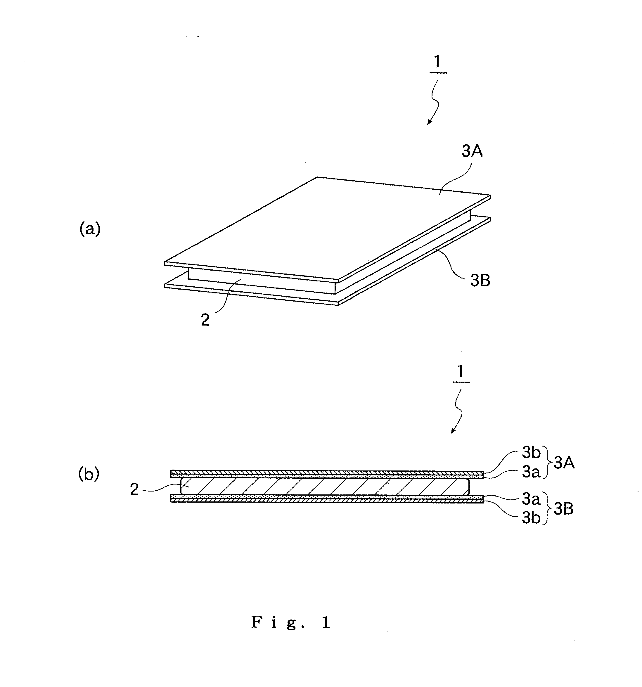
[0018]As shown in FIG. 1, a metal foil laminate 1 according to First Embodiment includes a square plate-shaped resin-impregnated base material 2 and square sheet-shaped copper foils 3 (3A, 3B) are integrally attached on both upper and lower surfaces of the resin-impregnated base material 2, respectively. Herein, as shown in FIG. 1B, each copper foil 3 has a two-layered structure including a matted surface 3a and a shine surface 3b, and is contacted with the resin-impregnated base material 2 at the side of the matted surface 3a. The size (one side of a square) of each copper foil 3 is slightly larger than that of the resin-impregnated ...

second embodiment

of the Invention

[0082]In FIG. 4, Second Embodiment of the present invention is shown. In Second Embodiment, three-stage configuration, namely, the case of producing three metal foil laminates by single hot pressing will be described. In FIG. 4, the respective members are shown in a state of being separated from each other for easy understanding.

[0083]The metal foil laminate 1 and the hot press device 11 according to Second Embodiment have the same constitution as that of First Embodiment.

[0084]When the metal foil laminate 1 is produced using this hot press device 11, three metal foil laminates 1 are simultaneously produced in accordance with the production procedure of the metal foil laminate 1 in First Embodiment, as described hereinafter.

[0085]First, in the first laminate production process, in the same manner as in First Embodiment, the resin-impregnated base material 2 is sequentially interposed between a pair of copper foils 3A, 3B and between a pair of spacer copper foils 5A, ...

example 1

[0104]Using the aforementioned heat-treated resin-impregnated base material, an aramid cushion (aramid cushion measuring 3 mm in thickness, 520 mm in length and 520 mm in width, manufactured by Ichikawa Techno-Fabrics Co., Ltd.), a SUS plate (SUS304, measuring 5 mm in thickness, 500 mm in length and 500 mm in width), a SUS plate (SUS304, measuring 1 mm in thickness, 500 mm in length and 500 mm in width), a spacer copper foil (“3EC-VLP” measuring 18 μm in thickness, manufactured by MITSUI MINING & SMELTING CO., LTD.), a copper foil constituting a metal foil laminate (“3EC-VLP” measuring 18 μm in thickness, 453 mm in length and 453 mm in width, manufactured by MITSUI MINING & SMELTING CO., LTD.), a resin-impregnated base material constituting a metal foil laminate (prepreg measuring 7 μm in thickness, 433 mm in length and 433 mm in width in which a glass cloth is impregnated with a liquid crystal polyester), a copper foil constituting a metal foil laminate (“3EC-VLP” measuring 18 μm i...


PUM

PropertyMeasurementUnit
thicknessaaaaaaaaaa
thicknessaaaaaaaaaa
temperatureaaaaaaaaaa

Abstract

The present invention provides a method for producing a metal foil laminate, the method comprising sequentially interposing an insulating base material between a pair of metal foils and between a pair of metal plates, followed by heating and pressurizing to produce a metal foil laminate in which the pair of metal foils are attached on both sides of the insulating base material, wherein the ratio of an area of the insulating base material to that of each metal plate is from 0.75 to 0.95. According to the present invention, tight adhesion of a metal foil laminate is sufficiently increased even if the metal foil laminate has a large size.

Description

BACKGROUND OF THE INVENTION[0001]1. Field of the Invention[0002]The present invention mainly relates to a method for producing a metal foil laminate which is used as a material for a printed circuit board.[0003]2. Description of the Related Art[0004]Multifunctionalization of electronic equipment has acceleratively advanced year by year. Because of such multifunctionalization, in addition to an improvement in a semiconductor package which has hitherto been made, higher performances have been required in a printed circuit board on which electronic components are mounted. For example, in order to meet requirements such as miniaturization and weighting saving of electronic equipment, the necessity of densification of a printed circuit board has been increasing. Thus, multilayering of a wiring substrate, narrowing of a wiring pitch and micromiaturization of via holes has advanced.[0005]A metal foil laminate, which is a material that has hitherto been used in this printed circuit board, h...

Claims


Application Information

Patent Timeline
Patent Type & Authority Applications(United States)
IPC IPC(8): C09J5/06
CPCC09J5/06B32B2457/08C09J2467/00B32B15/043B32B15/14B32B15/20B32B37/26B32B2037/262B32B2250/05B32B2250/40B32B2260/021B32B2260/046B32B2262/10B32B2262/101B32B2262/106B32B2305/076B32B2307/406B32B2307/408B32B2309/105B32B2309/68B32B2311/12C09J2400/163B29C43/18B29C43/32B32B15/09B32B37/10
Inventor AZAMI, SHOHEISHIM, CHANGBOITO, TOYONARI
Owner SUMITOMO CHEM CO LTD
Why Eureka
Try Eureka