Object detection device

a technology for object detection and detection devices, applied in measurement devices, instruments, vehicle components, etc., to achieve the effect of easy setting of search area and large search area

Inactive Publication Date: 2009-08-13
TOYOTA JIDOSHA KK
View PDF28 Cites 57 Cited by
  • Summary
  • Abstract
  • Description
  • Claims
  • Application Information

AI Technical Summary

Benefits of technology

[0009]In this object detection apparatus, the object position detection means detects the positions of the objects by using the plurality of position detection criteria. Also, in the object detection apparatus, the object type estimating means estimates the types of the objects based on the position detection criteria used for detecting the positions of the objects, for each object detected by the object position detection means. Therefore, because the search area is set based on the types of the objects, it is set based on the position detection criteria used for detecting the positions of the objects. For example, in the case in which an automobile and a pedestrian are to be detected, the automobile position detection criteria and the pedestrian position detection criteria are set in the object position detection means. When the position of an object is detected by the object position detection means using the pedestrian position detection criteria, the object type estimating means estimates the type of the object to be a pedestrian, and a search area is set based on the size of the pedestrian (<a search area based on the size of an automobile). Therefore, the size of the object that is obtained from the plurality of position detection results integrated in this search area is equal to or smaller than the size of the search area considering the size of the pedestrian, but does not significantly exceed the size of the pedestrian. In this manner, in this object detection apparatus, the position detection criteria linked to the types of the objects are provided so as to be able to estimate the types of the objects easily (consequently, the search area can be set easily for each type of object).
[0011]In this object detection apparatus, the radar sensor uses the plurality of position detection criteria to detect the positions of the objects (at least the positions in the horizontal direction) based on radar information. Moreover, in the object detection apparatus, the image sensor detects the positions of the objects (at least the positions in the horizontal direction) based on the captured images. In addition, in the object detection apparatus, for each of the objects detected by the radar sensor, the type of the each object is estimated based on the position detection criteria used for detecting the position of the object, and the search area is set based on the position of the object in the horizontal direction that is detected by the radar sensor and based on the position detection criteria used for detecting the position of the object. Moreover, in the object detection apparatus, the object estimating means integrates the position detection result obtained based on the radar information within each set search area and the position detection result obtained based on the captured images, and estimates the sizes of the objects in the horizontal direction by means of the plurality of the position detection results. In this manner, in the object detection apparatus, the radar sensor detects the positions of the objects by using the plurality of position detection criteria so that the search area can be set easily for each type of object, and that the sizes of the objects in the horizontal direction can be estimated at high precision by using the radar information and the captured images.
[0013]In this object detection apparatus, the radar sensor receives the reflected waves of the scanning electromagnetic waves from the objects, and the reception intensity is determined based on each of the plurality of position detection criteria (threshold values). Then, the search area is set by the object detection apparatus to be larger for the object detected with the threshold value of the large reception intensity than the object detected with the threshold value of the small reception intensity. Here, the position detection criteria are set based on the reflectance property of each type of object of the electromagnetic waves, hence a high reception intensity threshold value is set for the object having high reflectivity to the electromagnetic waves, and a small reception intensity threshold value is set for the object having low reflectivity to the electromagnetic waves. Moreover, not the object having low reflectivity to the electromagnetic waves but the object having high reflectivity are assumed to be the objects having high reflectivity to the electromagnetic waves, and a large search area is set therefor. For example, an automobile corresponds to the object having high reflectivity to the electromagnetic waves, and a pedestrian (person) corresponds to the object having low reflectivity to the electromagnetic waves. Therefore, in this object detection apparatus the search area can be set easily for each type of object by taking advantage of the fact that the reception intensity of the electromagnetic waves is different for each type of object.

Problems solved by technology

Therefore, when integrating a plurality of detection results in the same search area regardless of the type of the object, an excessive number of detection results might be integrated, which can possibly lead to estimation of the object to be larger than it actually is.

Method used


Image

  • Object detection device
  • Object detection device
  • Object detection device

Examples


Embodiment Construction

[0019]An embodiment of the object detection apparatus according to the present invention will be described hereinafter with reference to the drawings.

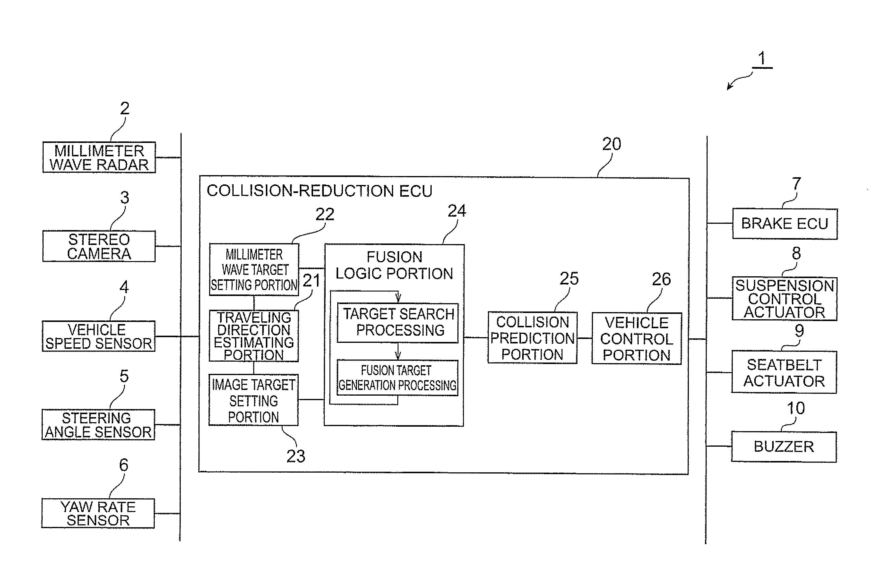
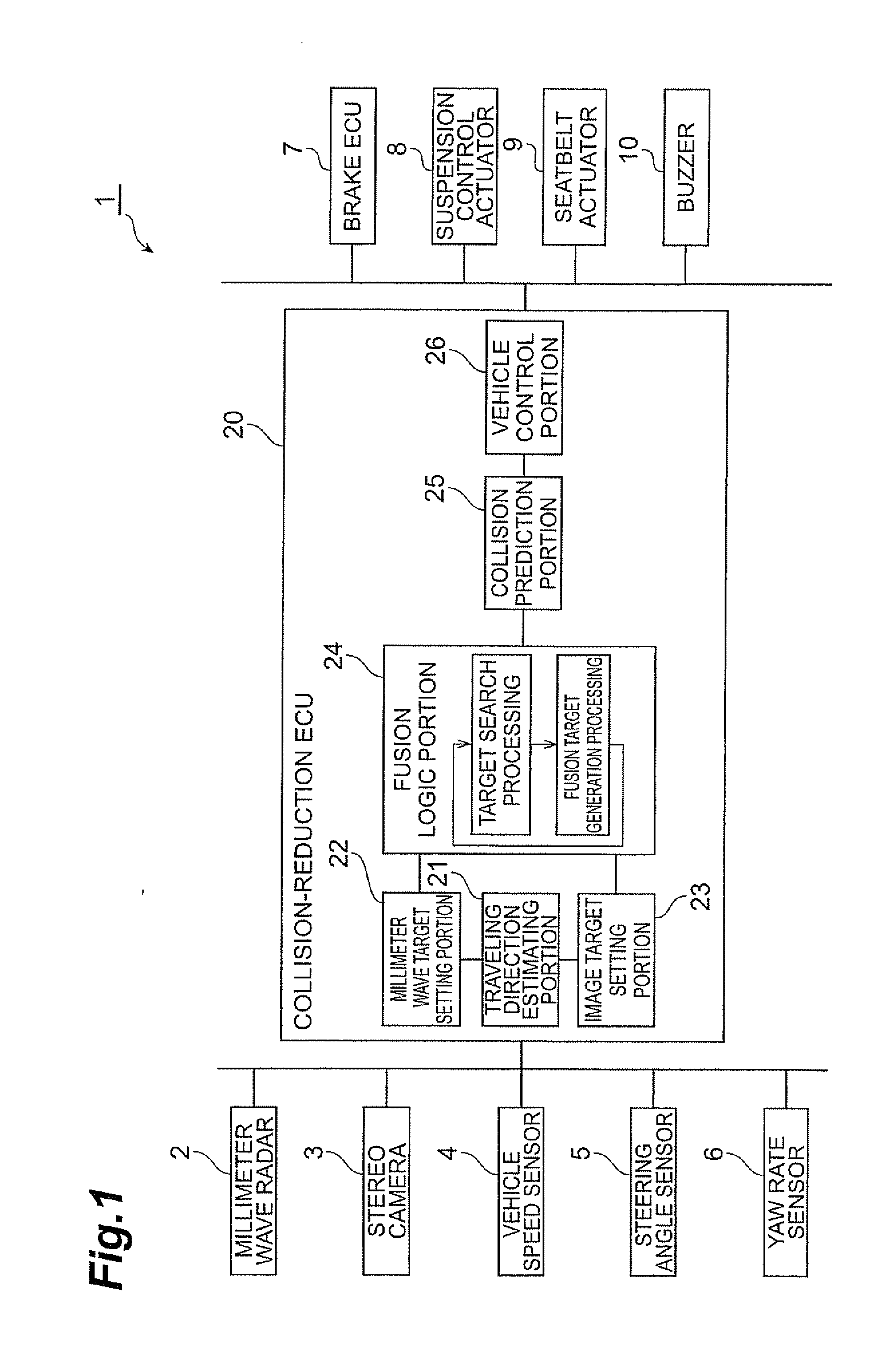
[0020]In the present embodiment, the object detection apparatus according to the present invention is applied to a collision-reduction apparatus mounted in a vehicle. The collision-reduction apparatus according to the present embodiment detects an automobile or pedestrian in front as a detected matter, and performs various control for preventing / reducing collision with the detected object. Particularly, the collision-reduction apparatus according to the present embodiment has two detection means, i.e., millimeter wave radar and a stereo camera, for detecting a front object, and thereby detects a front object by checking an object detected by the millimeter wave radar against an object detected by the stereo camera.

[0021]The collision-reduction apparatus 1 will now be described with reference to FIG. 1 through FIG. 3. FIG. 1 is a config...


PUM


Abstract

An object of the present invention is to provide an object detection apparatus capable of detecting an object at high precision in accordance with the type of the object. The object detection apparatus of the present invention comprises: object position detection means 2, 22, 3, 23 for detecting the positions of objects; object type estimating means 24 for estimating the types of the objects; and object estimating means 24 for integrating a plurality of detection results for positions within a search area obtained by the object position detection means 2, 22, 3, 23 and thereby estimating the sizes of the objects, the object detection apparatus of the present invention being characterized in that the search area is set based on the types of the objects estimated by the object type estimating means 24. Moreover, the object detection apparatus of the present invention is characterized in that the object position detection means 2, 22, 3, 23 detects the positions of the objects by using a plurality of position detection criteria, that the object type estimating means 24 estimates the types of the objects based on the position detection criteria, according to which the object position detection means 2, 22, 3, 23 have been able to detect the positions of the objects, and that the search area is set based on the position detection criteria, according to which the positions of the objects have been detected.

Description

TECHNICAL FIELD[0001]The present invention relates to an object detection apparatus which detects objects based on a plurality of position detection results.BACKGROUND ART[0002]In recent years, driving support apparatuses such as collision-reduction apparatuses, inter-vehicle distance control apparatuses and follow-up traveling apparatuses have been developed. It is important for these driving support apparatuses to detect a vehicle traveling in front of a host vehicle. Among the object detection apparatuses, there is an apparatus having two detection means in order to improve detection accuracy: detection means that uses radar and detection means that uses images captured by a stereo camera or the like (see Japanese Unexamined Published Patent Application No. 2003-44995, for example). In the object detection apparatus with these two detection means, a radar-detected object detected based on radar information is checked against an image-detected object detected based on image inform...

Claims


Application Information

Patent Timeline
Patent Type & Authority Applications(United States)
IPC IPC(8): G01S13/93G01S13/931
CPCB60R21/0134B60R2021/01313B60R2021/01327B60W30/09B60W30/095G01S2013/9375B60W2420/52G01S13/931G01S13/867G01S2013/9346G01S2013/9353B60W2420/42G01S2013/93185G01S2013/93271G01S2013/932
Inventor TOKORO, SETSUOTSUCHIDA, JUN
Owner TOYOTA JIDOSHA KK
Why Eureka
Try Eureka