Speaker device

Inactive Publication Date: 2009-08-13
PANASONIC CORP
0 Cites 2 Cited by

AI-Extracted Technical Summary

Problems solved by technology

This has led to adoption of a resin as a lightweight material also for the box that forms t...

Method used

[0023]Further, acoustic space 12 of this speaker device is formed by baffle plate 1 and back cover 4. Each of baffle plate 1 and back cover 4 is a resin formed body, and a tabular central portion of an upper surface of baffle plate 1 is integrated with speaker 3. Baffle plate 1 has opening 2 to be used as a frame of speaker 3. It should be noted that examples of the resin formed body may include polyphthalamide and super-heat resistant ABS. Further, step 13 is provided at a side surface of opening 2 of baffle plate 1. In this structure, diaphragm 7 is positioned by use of step 13 in fixing of diaphragm 7, and magnetic circuit 5 is fixed to a portion extended from step 13. Formation of step 13 in opening 2 of baffle plate 1 leads to formation of a protrusion at a side of acoustic space 12 (i.e. back surface side of speaker 3) of baffle plate 1. This protrusion functions as a rib structure of soft baffle plate 1 formed by resin molding. As thus described, by providing step 13, it is possible to obtain effects of improving an action of positioning diaphragm 7 and strength of baffle plate 1. This can result in improvement in strength of a small-sized lightweight speaker device.
[0024]Moreover, it is known that such a speaker device is provided with a bass-reflex port in order to enhance an acoustic characteristic. In the present embodiment, through ...

Benefits of technology

[0004]The present invention provides a speaker device having: a speaker including a magnetic circuit, a voice coil driven by the magnetic circuit, and a diaphragm with its inner peripheral end connected to the voice coil; a baffle plate made of a resin and having an opening that connects an outer peripheral end of the diaphragm; and a back cover connected with an outer peripheral end of the baffle...

Abstract

There is provided a speaker device in which a baffle plate that forms an acoustic space is formed of a resin material, and a step is provided at an opening for fixing a diaphragm in this baffle plate so that the diaphragm is positioned by this step. It is thereby possible to improve strength of the baffle plate and strength of the speaker device.

Application Domain

Single transducer incorporationFrequency/directions obtaining arrangements +1

Technology Topic

Image

  • Speaker device
  • Speaker device
  • Speaker device

Examples

  • Experimental program(1)

Example

[0021]In the following, one exemplary embodiment of the present invention is described with reference to drawings. The drawings are schematic views, and are thus not views showing positional relationships in a dimensionally accurate manner. Further, the present invention is not limited to the embodiment.
Embodiment
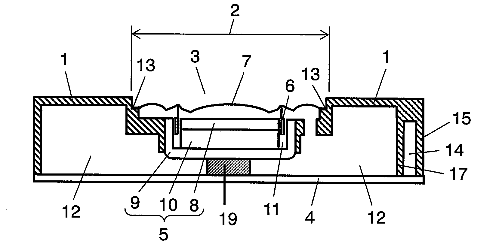
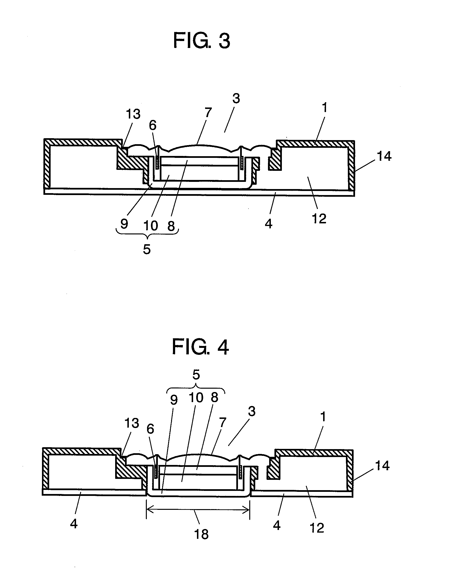
[0022]FIG. 1 is a sectional view showing a speaker device of the present invention. A fundamental structure is that speaker 3 is connected to opening 2 of baffle plate 1, and a back surface side of speaker3 is covered with back cover 4. Speaker 3 is formed of magnetic circuit 5, voice coil 6 and diaphragm 7. Magnetic circuit 5 is configured by arrangement of magnet 10 between upper plate 8 and yoke 9. Voice coil 6 is provided at magnetic gap 11 formed between an extended portion of yoke 9 and upper plate 8. An audio signal is inputted into voice coil 6 to drive voice coil 6. In this structure, diaphragm 7 is vibrated with driving of voice coil 6 to emit a sound.
[0023]Further, acoustic space 12 of this speaker device is formed by baffle plate 1 and back cover 4. Each of baffle plate 1 and back cover 4 is a resin formed body, and a tabular central portion of an upper surface of baffle plate 1 is integrated with speaker 3. Baffle plate 1 has opening 2 to be used as a frame of speaker 3. It should be noted that examples of the resin formed body may include polyphthalamide and super-heat resistant ABS. Further, step 13 is provided at a side surface of opening 2 of baffle plate 1. In this structure, diaphragm 7 is positioned by use of step 13 in fixing of diaphragm 7, and magnetic circuit 5 is fixed to a portion extended from step 13. Formation of step 13 in opening 2 of baffle plate 1 leads to formation of a protrusion at a side of acoustic space 12 (i.e. back surface side of speaker 3) of baffle plate 1. This protrusion functions as a rib structure of soft baffle plate 1 formed by resin molding. As thus described, by providing step 13, it is possible to obtain effects of improving an action of positioning diaphragm 7 and strength of baffle plate 1. This can result in improvement in strength of a small-sized lightweight speaker device.
[0024]Moreover, it is known that such a speaker device is provided with a bass-reflex port in order to enhance an acoustic characteristic. In the present embodiment, through hole 16 is provided at outer peripheral side wall portion 15 of baffle plate 1, and partition wall 17, which protrudes from through hole 16 along outer peripheral side wall portion 15 so as to come in contact with back cover 4, is provided. As shown in FIG. 2, an acoustic path, which extends from acoustic space 12 formed by partition wall 17 and outer peripheral side wall portion 15 to through hole 16, is configured as bass-reflex port 14. With this configuration, outer peripheral side wall portion 15 and partition wall 17 provided at baffle plate 1 function as a rib structure of the upper surface of soft baffle plate 1 as the resin formed body, to improve the strength of baffle plate 1. This can result in improvement in strength of the small-sized lightweight speaker.
[0025]It should be noted that in the speaker device of the present embodiment, buffer member 19 is provided between a bottom surface of magnetic circuit 5 and back cover 4 for suppressing deterioration in acoustic characteristic due to vibrations of speaker 3 itself. For realizing further reduction in height, a structure may be employed as shown in FIG. 3 in which the bottom surface of magnetic circuit 5 is brought into contact with back cover 4. Moreover, as shown in FIG. 4, through hole 18 may be provided at back cover 4 to fit the bottom of magnetic circuit 5 in through hole 18.
INDUSTRIAL APPLICABILITY
[0026]The present invention has an effect of enhancing mechanical strength in a speaker device having been reduced in size and weight. Further, the present invention is effective especially as a speaker device used for small-sized electrical instrument such as a mobile phone.

PUM

no PUM

Description & Claims & Application Information

We can also present the details of the Description, Claims and Application information to help users get a comprehensive understanding of the technical details of the patent, such as background art, summary of invention, brief description of drawings, description of embodiments, and other original content. On the other hand, users can also determine the specific scope of protection of the technology through the list of claims; as well as understand the changes in the life cycle of the technology with the presentation of the patent timeline. Login to view more.

Similar technology patents

Chromia-alumina refractory

ActiveUS20100019419A1Improved strengthLowering of permeabilityCeramic shaping apparatusClaywaresMaterials scienceRefractory
Owner:HARBISON WALKER REFRACTORIES

Rivet tool for steel studs

InactiveUS20090038137A1Improved strengthGood bondingGirdersJoistsWall plateFastener
Owner:HASSENZAHL ROBERT D

Electroconductive paste with adhesion enhancer

Owner:HERAEUS PRECIOUS METALS NORTH AMERICA CONSHOHOCKEN

Classification and recommendation of technical efficacy words

Why Eureka
Try Eureka