
Surgical cable with malleable leader segment

Inactive Publication Date: 2009-08-13
KINAMED
View PDF10 Cites 23 Cited by
  • Summary
  • Abstract
  • Description
  • Claims
  • Application Information

AI Technical Summary

Benefits of technology

[0008]A surgical cable having a malleable leader segment is presented, in which the leader segment facilitates the manipulation of the cable around and through anatomical structures.
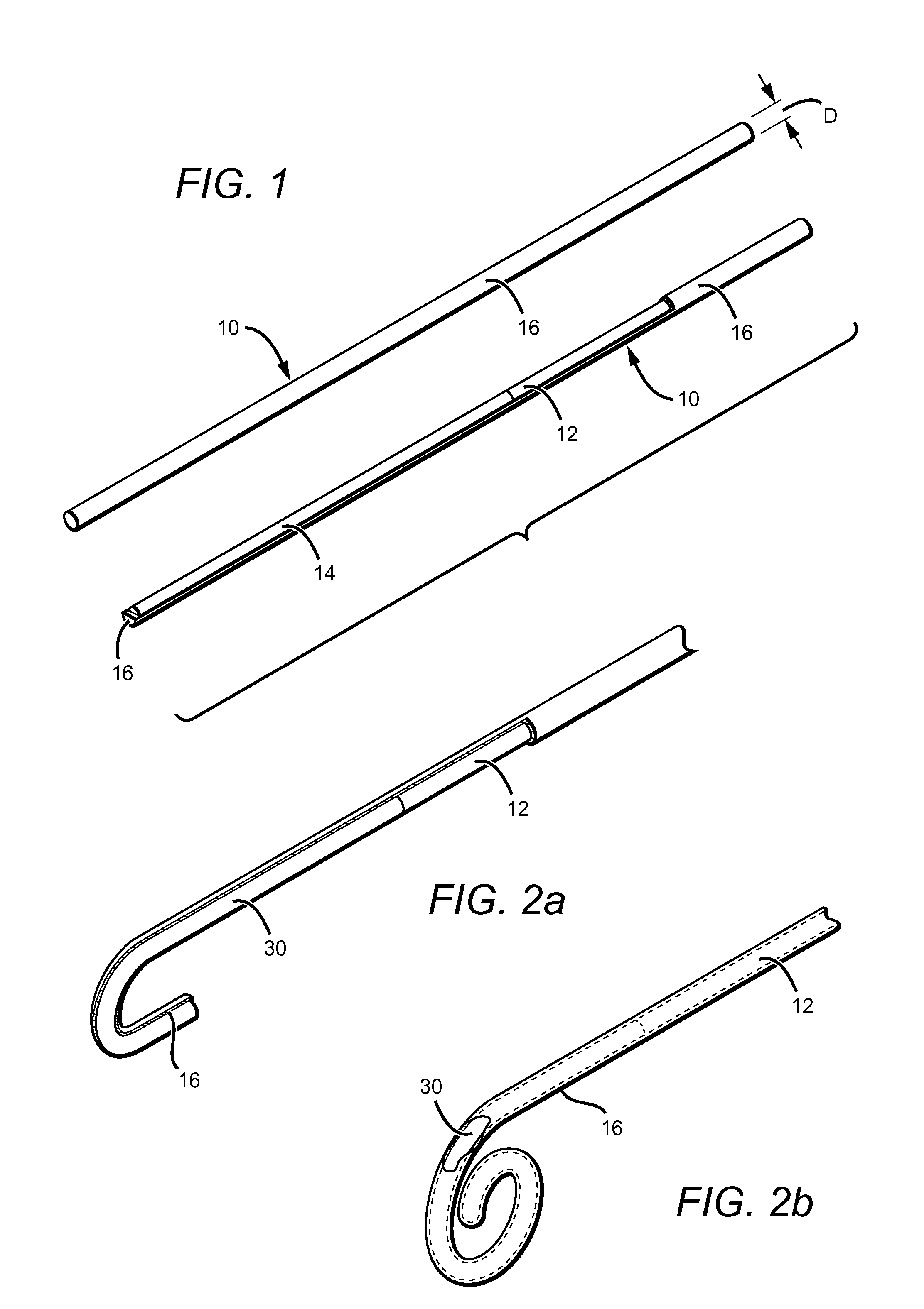
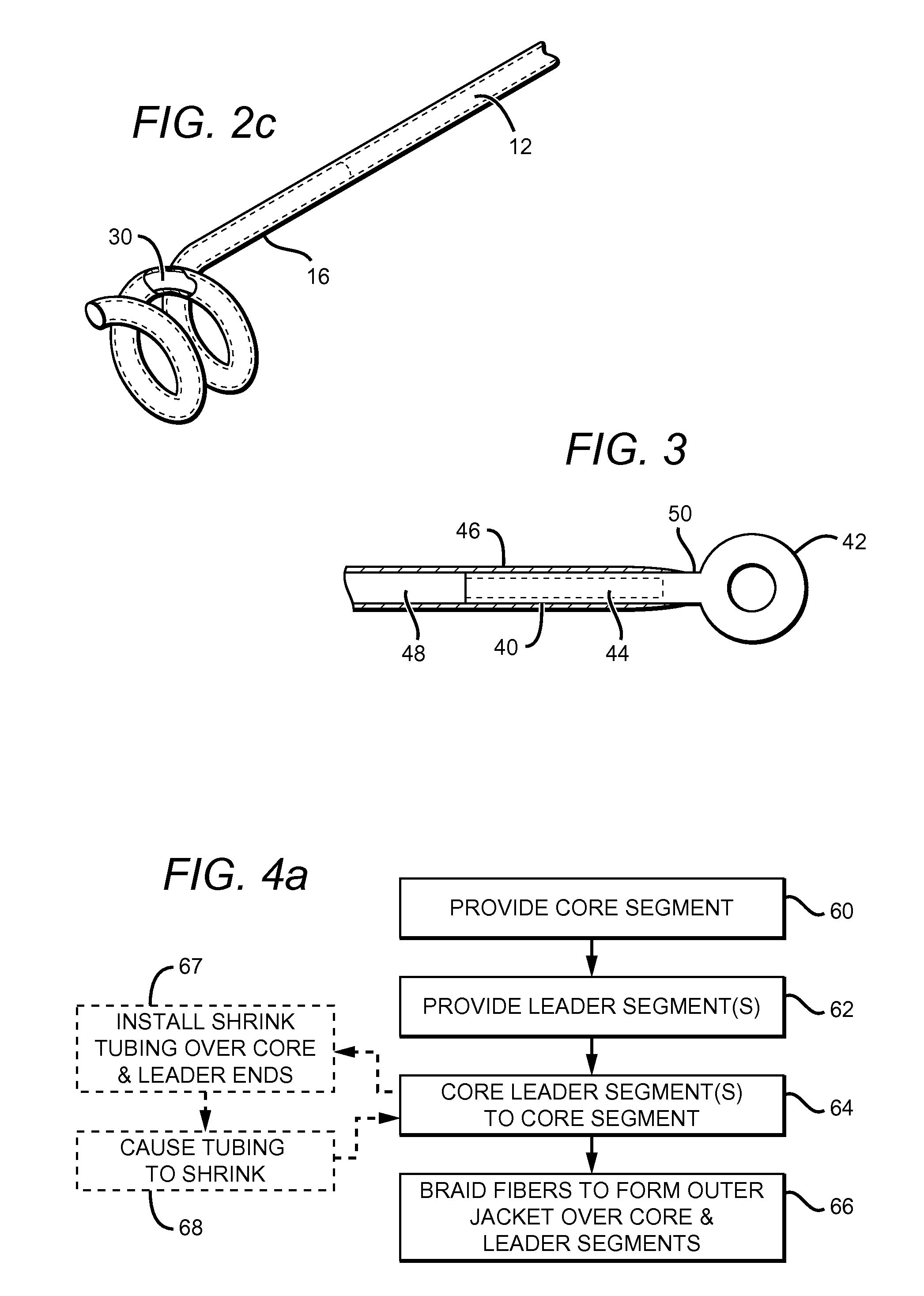
[0010]When so arranged, the leader segments enable the cable to be more easily manipulated around and through anatomical structures. The cable is manipulated by means of the leader segments, which are preferably capable of resisting bending in response to head-on compression, at least to the extent needed to push through soft tissues or minor obstructions under manual pressure. Leader segments are preferably located at or near one or both ends of the cable. The core and leader segments are preferably encapsulated within the outer jacket, which is facilitated by ensuring that the leader segment diameter is approximately equal to or less than the diameter of the core segment. If desired, a leader segment can be preformed into a desired shape, such as a J-hook, helix, spiral or eyelet shape.

Problems solved by technology

This requires the cable's leading end to be manipulated by the surgeon, which can be extremely challenging when working in tightly confined spaces, particularly those near highly delicate areas such as the spinal column.
However, this approach can be problematic, especially when employed with a cable that features an inner core encapsulated in a braided outer jacket.
Unfortunately, the diameter of the portion of the needle overlapping the core would necessarily be larger than that of the core, thereby complicating the installation of the outer jacket and possibly rendering the cable unsuitable for some applications.
A needle might alternatively be swaged onto the cable over the outer jacket; however, this could risk damage to the jacket and unacceptably increase the effective outer diameter of the cable construct.

Method used


Image

  • Surgical cable with malleable leader segment
  • Surgical cable with malleable leader segment
  • Surgical cable with malleable leader segment

Examples


Embodiment Construction

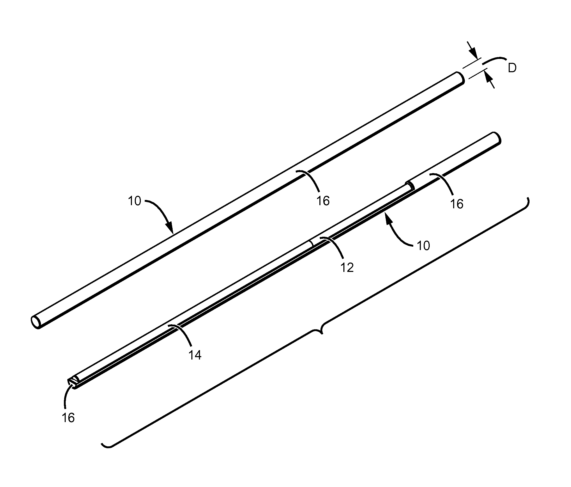
[0020]FIG. 1 shows a first embodiment of a surgical cable in accordance with the present invention. Two views are shown: one shows an intact cable 10, and the other shows cable 10 with its outer jacket partially cut away to reveal its core and “leader” segments.

[0021]The cable comprises a core segment 12, made from a material having a high tensile strength and capable of elongation, at least one leader segment 14 arranged axially in tandem with core segment 12 and made from a semi-rigid ductile material such that it is malleable—i.e., capable of being manipulated into a desired shape. The cable also includes a plurality of braided fibers that form an outer jacket 16 which surrounds the core segment and at least a portion of leader segment 14. Outer jacket 16 preferably comprises woven or braided fibers made from a high strength, low stretch protective material; a polymer material such as ultra-high molecular weight polyethylene (UHMWP), is preferred. Providing a leader segment made ...


PUM


Abstract

A surgical cable comprises a core segment, at least one leader segment, and an outer jacket. The core segment is made from a material having a high tensile strength and which is capable of elongation. Each leader segment is arranged axially in tandem with the core segment and comprises a semi-rigid ductile material capable of being manipulated into a desired shape. A plurality of braided fibers form the outer jacket, which surrounds the core segment and at least a portion of the leader segment. The cable is manipulated by means of the leader segments, which are preferably capable of resisting bending in response to head-on compression, thereby enabling the cable to be more easily manipulated around and through anatomical structures.

Description

RELATED APPLICATIONS[0001]This application claims the benefit of provisional patent application No. 61 / 065,724, filed Feb. 13, 2008.BACKGROUND OF THE INVENTION[0002]1. Field of the Invention[0003]This invention relates generally to surgical cables, and more particularly, to means by which such cables can be more easily manipulated around and through anatomical structures.[0004]2. Description of the Related Art[0005]Many products are known which serve to hold human body tissues and bones in a desired relationship or position, to aid in their healing when injured or diseased. One such product is the surgical cable, which is wrapped around one or more tissues and / or bones as needed. For example, a surgical cable can be wrapped around the fragments of a fractured bone, such that a compressive force is applied which aids in the healing of the bone. Such a cable is described, for example, in U.S. Pat. No. 6,589,246 to Hack et al.[0006]Cables of this sort must be threaded around and throug...

Claims


Application Information

Patent Timeline
IPC IPC(8): A61B17/68
CPCA61B17/82A61B2017/00946A61B17/842
Inventor PRATT, WILLIAM RALPH
Owner KINAMED
Learn More