Obstetrical vacuum extractor with over-traction release

a vacuum extractor and vacuum technology, applied in the field of vacuum extractors, can solve problems such as the breaking of the blood vessels connecting the fetal scalp from its underlying surfa

Inactive Publication Date: 2009-08-13
ROSS MICHAEL G
View PDF6 Cites 19 Cited by
  • Summary
  • Abstract
  • Description
  • Claims
  • Application Information

AI Technical Summary

Problems solved by technology

These extractors are often used when spontaneous vaginal delivery is not possible or is unsuccessful.
However, in some situations excessive force has been applied d...

Method used


Image

  • Obstetrical vacuum extractor with over-traction release
  • Obstetrical vacuum extractor with over-traction release
  • Obstetrical vacuum extractor with over-traction release

Examples


Embodiment Construction

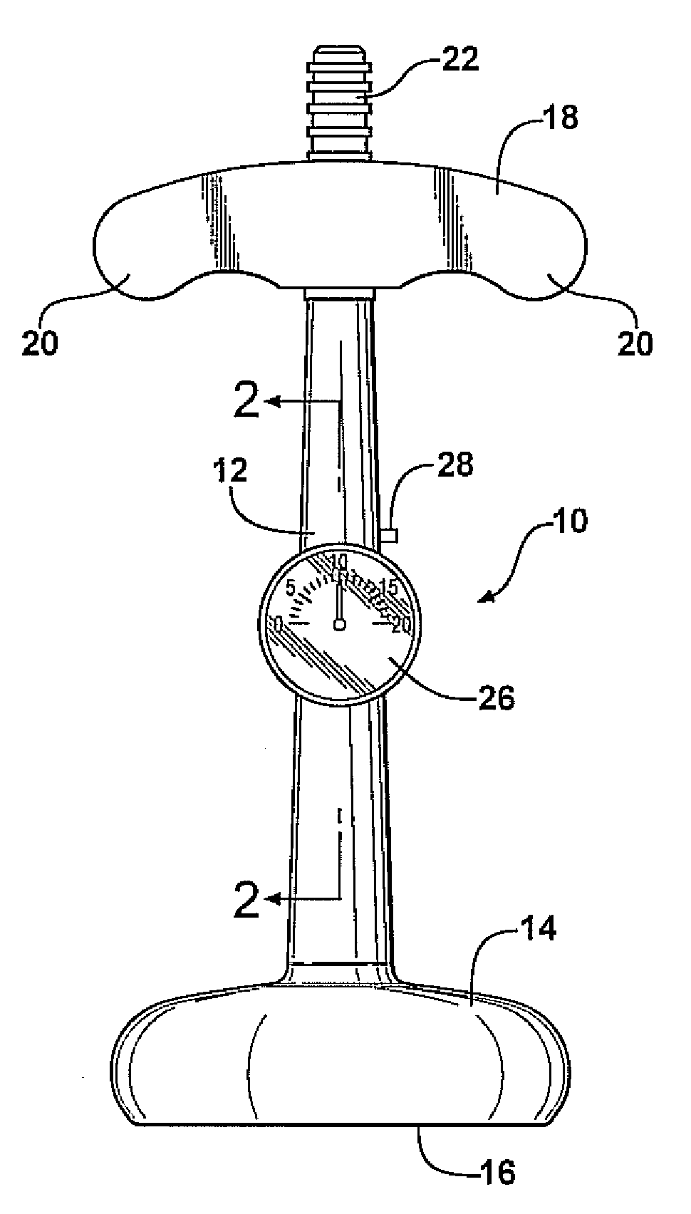
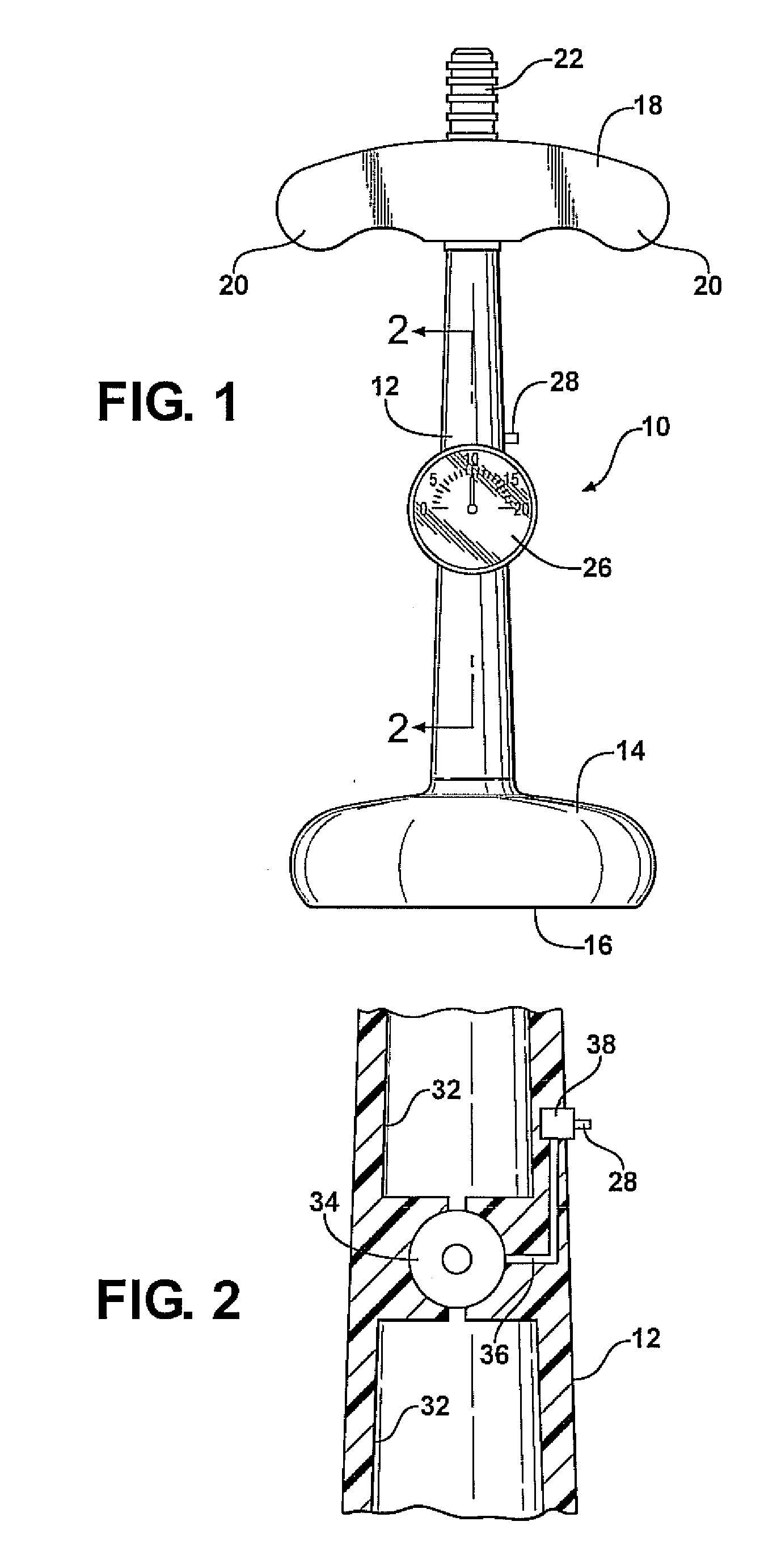
[0012]Referring to the drawings, FIG. 1 illustrates a preferred embodiment of my invention constructed on an obstetrical vacuum extractor of the general type illustrated in U.S. Pat. No. 5,019,086. The extractor, generally indicated at 10, has an elongated hollow stem 12, preferably formed of plastic. The lower end of the stem, as illustrated in FIG. 1, is connected to a resilient cup 14 which is open at its lower end 16. The cup is formed as a shell and the interior of the cup 14 communicates with the hollow section of the stem 12.

[0013]In alternate embodiments of the invention the cup 14 can be rigid and made of metal, although resilient cups are more popular with obstetricians.

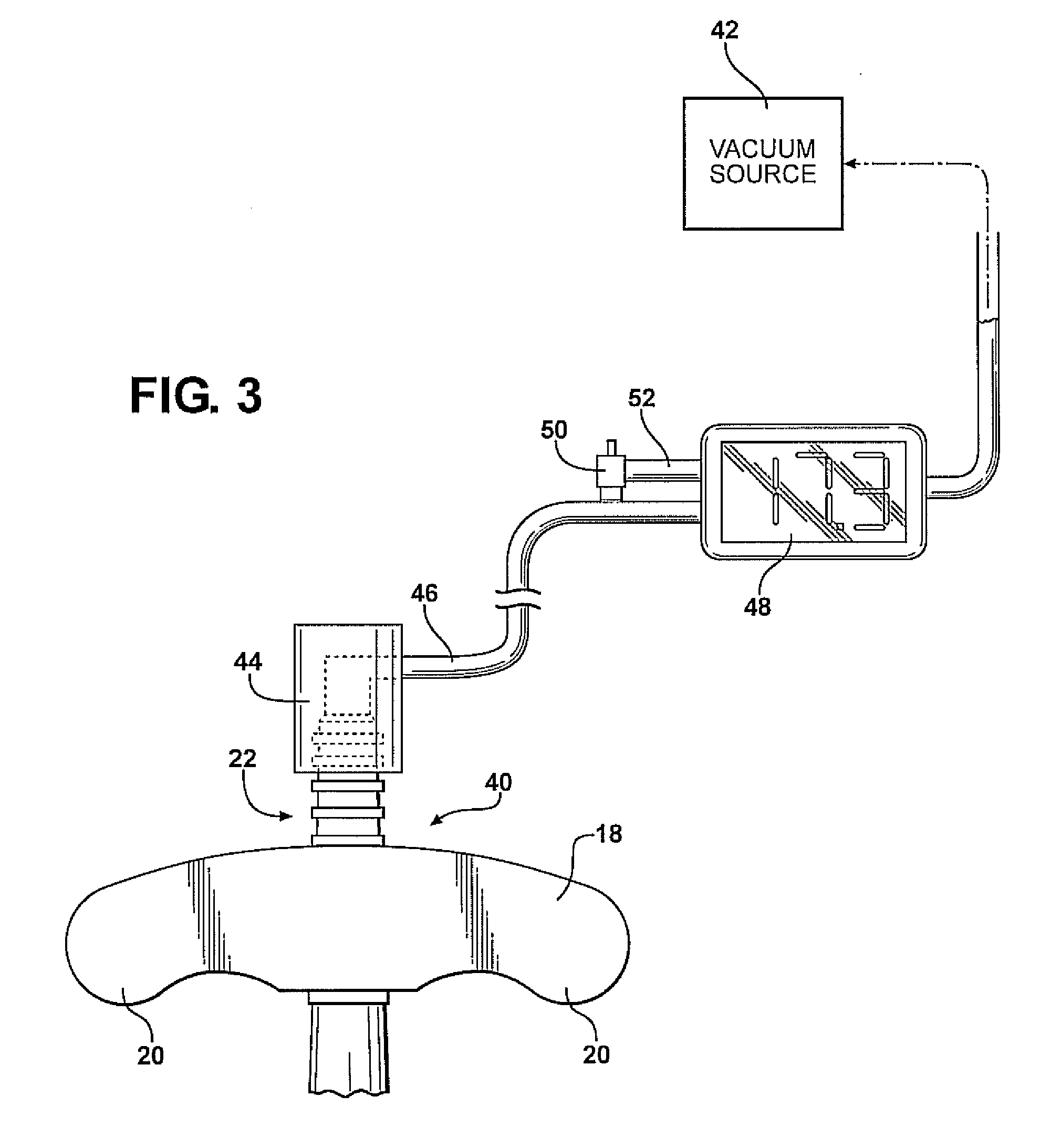
[0014]The upper end of the stem 12 is connected to a rigid handle 18 consisting of two ears 20 which project on opposite sides of the connection of the handle to the stem. The upper end of the hollow within the stem is joined to a connector 22 which is adapted to receive a flexible vacuum hose (not shown). ...


PUM


Abstract

A vacuum extractor for obstetrical use comprises a vacuum cup at one end of an elongated stem having a handle at the opposite end. The vacuum cup is sealed over a portion of the head of the fetus and a vacuum source, usually operating through the stem, connects to the inner side of the cup and secures it to the fetal head. A strain sensor is connected to the stem. When the force applied to the cup through the handle and stem exceeds a predetermined maximum, a valve connecting the vacuum pressure to the atmosphere is opened so as to release the vacuum pressure from the cup.

Description

CROSS-REFERENCE TO RELATED APPLICATIONS[0001]This application claims priority of U.S. Provisional Patent Application Ser. No. 61 / 028,243 filed Feb. 13, 2008, which is incorporated herein by reference.FIELD OF THE INVENTION[0002]This invention relates to an improved vacuum extractor for childbirth including a vacuum cup connected to a handle through a stem and more particularly to such an extractor including a traction gauge which measures the extraction force applied to the fetus through the cup and releases the vacuum on the cup when the extraction force exceeds a predetermined value.BACKGROUND OF THE INVENTION[0003]Vacuum extractors have long been used as a tool to assist delivery, primarily in vaginal deliveries. These extractors are often used when spontaneous vaginal delivery is not possible or is unsuccessful. They typically employ a bell shaped vacuum cup connected to a handle that is used to apply a tractive force to the cup with a tube being connected by an elongated stem. ...

Claims


Application Information

Patent Timeline
IPC IPC(8): A61B17/42
CPCA61B17/442A61B2017/447A61B2017/445
Inventor ROSS, MICHAEL G.
Owner ROSS MICHAEL G
Why Eureka
Try Eureka