Self-expandable stent with a constrictive coating and method of use

a self-expanding, stent technology, applied in the field of self-expanding stents, can solve the problems of significant friction between the outer surface of the stent and the delivery sheath, high frictional force of the longer stent, and significant frictional force, so as to achieve high shear force, significant frictional force, and high shear force

Inactive Publication Date: 2009-08-13
BOSTON SCI SCIMED INC
View PDF7 Cites 75 Cited by
  • Summary
  • Abstract
  • Description
  • Claims
  • Application Information

AI Technical Summary

Benefits of technology

[0006]The present invention provides a system and method for providing and deploying a self-expandable medical device, such as a stent, without damaging the coating.
[0007]During loading and deployment of self-expandable stents, there may be significant friction between the stent outer surface and the delivery sheath. Because the self-expandable stent has a tendency to want to expand to its relaxed state, the stent presses radially outward against the inner surface of the sheath. Thus, when the stent is being loaded into and / or deployed out of the sheath, the frictional forces may be significant. Additionally, longer stents may have higher frictional forces. When the self-expandable stents have a coating on the outer surface, these forces may damage the coating. A coating on the outer surface of the self-expandable stent that is in contact with the inner surface of a delivery sheath is subject to high shear forces during both loading and deployment. Therapeutic agent coatings for medical devices may be relatively soft, for example consisting of a mixture of biodegradable or biostable polymers and drugs, or solely drugs. Particularly, such a soft coating can easily be stripped or damaged by contact with a delivery sheath during loading or deployment.
[0008]The present invention provides a system and method for providing a coating on a self-expandable medical device, such as a stent, while avoiding the issues relating to coating damage from the delivery sheath during loading and deployment. In one embodiment, the present invention comprises a constrictive coating that acts as a constrictive sheath for the stent during delivery and serves as a stent coating upon deployment. During delivery, the coating constrains the stent and is not pressed by the stent's expansion forces against the inner surface of the delivery tube. Thus, there is limited frictional force between the delivery tube surrounding the stent and the coating on the stent. A cutting mechanism is mounted on the end of the delivery tube such that when the stent with the constrictive coating exits the delivery tube, the constrictive coating is cut. This releases the constriction retaining the stent and the stent self-expands, pressing the cut portions of the coating against the lumen wall. A constrictive coating in accordance with one embodiment of the invention may have one or more of the following advantages: (1) being able to extend the coating proximally and / or distally of the stent, (2) assuring the coating is only abluminal, and / or (3) controlling the amount of therapeutic agent to be delivered to the body lumen in the coating. Additionally, the delivery tube can be much thinner than traditional delivery tubes, since it does not have to oppose the outward radial force of the stent, resulting in a more flexible system. Also, because the delivery tube can be thinner, the overall profile can be similar to or even smaller than existing systems, despite the presence of the constrictive coating.

Problems solved by technology

During loading and deployment of self-expandable stents, there may be significant friction between the stent outer surface and the delivery sheath.
Thus, when the stent is being loaded into and / or deployed out of the sheath, the frictional forces may be significant.
Additionally, longer stents may have higher frictional forces.
When the self-expandable stents have a coating on the outer surface, these forces may damage the coating.
A coating on the outer surface of the self-expandable stent that is in contact with the inner surface of a delivery sheath is subject to high shear forces during both loading and deployment.
Particularly, such a soft coating can easily be stripped or damaged by contact with a delivery sheath during loading or deployment.

Method used


Image

  • Self-expandable stent with a constrictive coating and method of use
  • Self-expandable stent with a constrictive coating and method of use
  • Self-expandable stent with a constrictive coating and method of use

Examples


Embodiment Construction

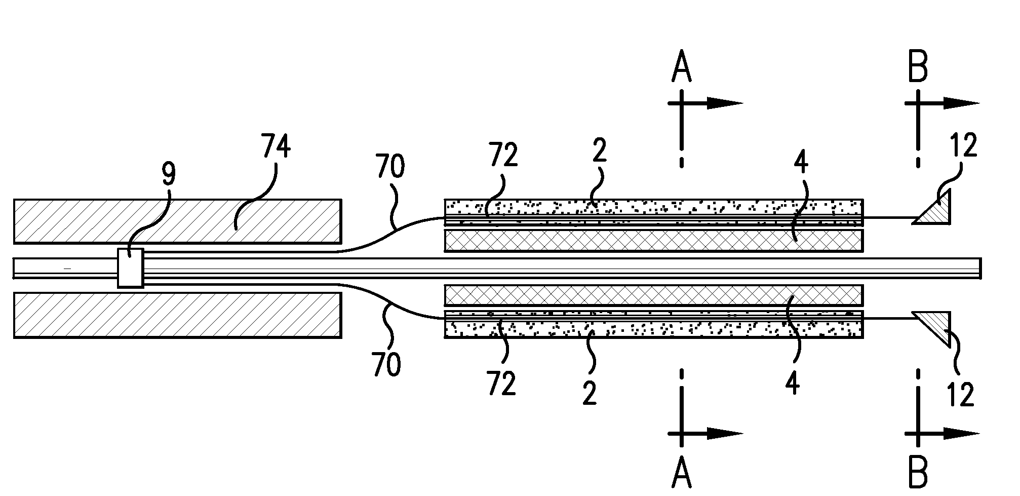
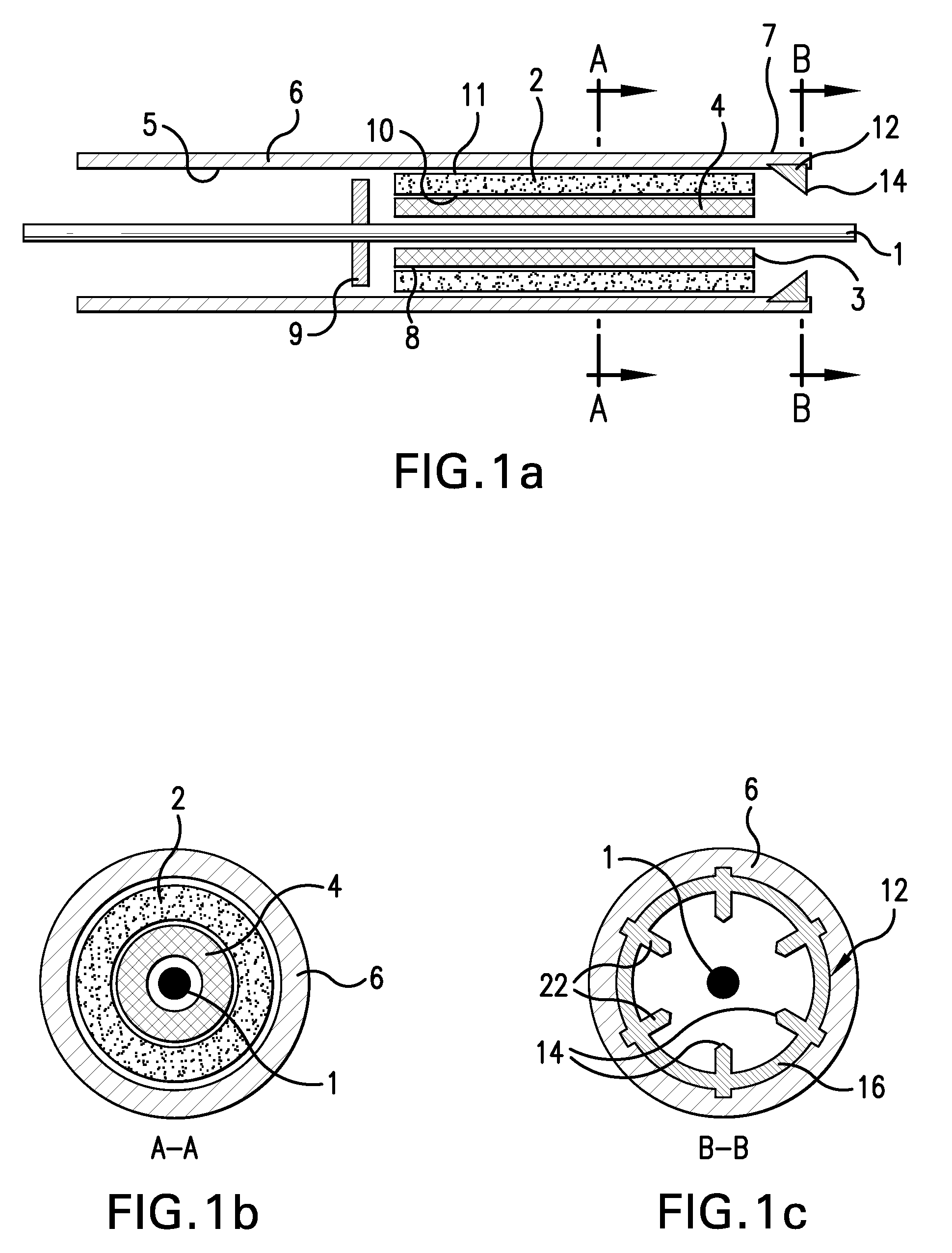
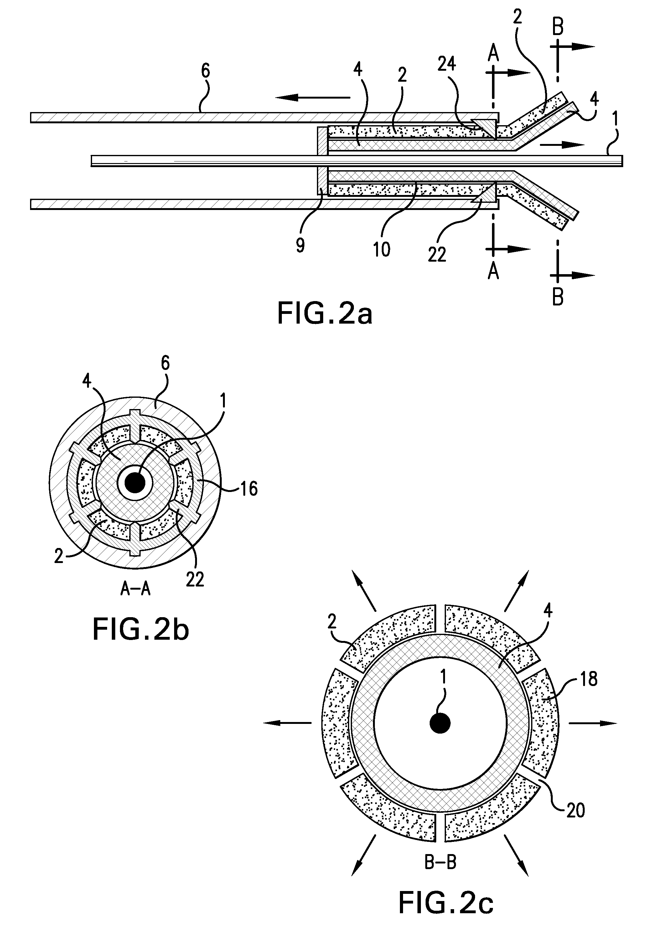
[0017]FIGS. 1a-1c and 2a-2c show an embodiment of a stent deployment system for deploying a self-expandable stent with a coating. The system comprises a constrictive coating 2 and a self-expandable stent 4, both housed within a delivery tube 6. Since the constrictive coating 2 prevents the self-expandable stent 4 from expanding to its unconstrained form, the stent 4 does not press the coating 2 against the delivery tube 6 with great force. In this embodiment, there is a small clearance space between the coating 2 and the delivery tube 6. Furthermore, if the coating 2 does abut the delivery tube 6, there will be little to no shear forces that could cause damage to the coating 2. A cutting mechanism 12 in the form of an annular ring 16 of blades 22 is mounted at the distal end 7 of the delivery tube 6. A guidewire 1 is used for delivering the stent deployment system to the implantation site within the body. In this embodiment, the guidewire 1 has a proximal stop 9, to assist in the de...


PUM

PropertyMeasurementUnit
wall thicknessaaaaaaaaaa
circumferenceaaaaaaaaaa

Abstract

The present invention provides a system and method for providing a coating on a self-expandable medical device, such as a stent, while avoiding the issues relating to coating damage from the delivery sheath during loading and deployment. In one embodiment, the present invention comprises a constrictive coating that acts as a constrictive sheath for the stent. A cutting mechanism is mounted on the end of the delivery tube such that when the stent with the constrictive coating exits the delivery tube, the constrictive coating is cut. This releases the constriction retaining the sheath, and the stent self-expands, pressing the cut portions of the coating against the lumen wall.

Description

CROSS REFERENCE TO RELATED APPLICATION[0001]The present application claims priority to U.S. provisional application Ser. No. 61 / 027,608 filed Feb. 11, 2008, the disclosure of which is incorporated herein by reference in its entirety.FIELD OF INVENTION[0002]The present invention relates to coated self-expanding stents and methods of delivering such stents.BACKGROUND[0003]Medical devices may be coated so that the surfaces of such devices have desired properties or effects. For example, it may be useful to coat medical devices to provide for the localized delivery of therapeutic agents to target locations within the body, such as to treat localized disease (e.g., heart disease) or occluded body lumens. Localized drug delivery may avoid some of the problems of systemic drug administration, which may be accompanied by unwanted effects on parts of the body which are not to be treated. Additionally, treatment of the afflicted part of the body may require a high concentration of therapeutic...

Claims


Application Information

Patent Timeline
Patent Type & Authority Applications(United States)
IPC IPC(8): A61F2/06A61B17/32
CPCA61B2017/32004A61F2/07A61L31/14A61F2250/0067A61L31/10A61F2/97
Inventor WEBER, JAN
Owner BOSTON SCI SCIMED INC
Why Eureka
Try Eureka