Advanced Electro-Active Optic Device

Active Publication Date: 2009-08-13
EA3TECH LLC +1
View PDF4 Cites 204 Cited by
  • Summary
  • Abstract
  • Description
  • Claims
  • Application Information

AI Technical Summary

Benefits of technology

[0016]An ophthalmic device as described herein may include an aperture, a peripheral region, a first transparent electrode having a plurality of pixel regions and a second transparent electrode disposed over the first transparent electrode, and an electro-active layer disposed between the first electrode and the second electrode, the electro-active layer including a material that allows for a variable transmission of light. The pixel regions may be individually addressable. The optical transmission of the aperture, the peripheral re

Problems solved by technology

In a presbyopic individual, this loss of accommodation first results in an inability to focus on near distance objects and later results in an inability to focus on intermediate distance objects.
In an aphakic individual, the absence of the crystalline lens causes a complete loss of accommodation that results in an inability to focus on either near or intermediate distance objects.
Additionally, the inlay is usually only be implanted in one eye as deleterious optical effects such as halos, doubling of vision, light scattering, glare, loss of contrast sensitivity, and/or reduction of light hitting the retina are too great and may be unacceptable when the inlay is implanted in both eyes.
These deleterious effects are caused by the size of the inlay's aperture and occluded annulus in relation to the size of the pupil.
However, each of these approaches for correcting presbyopia and/o

Method used


Image

  • Advanced Electro-Active Optic Device
  • Advanced Electro-Active Optic Device
  • Advanced Electro-Active Optic Device

Examples


Example

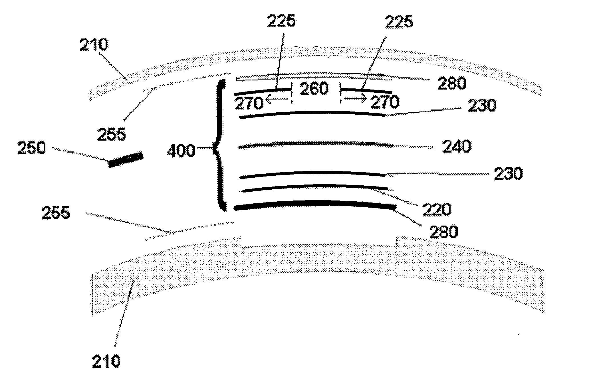
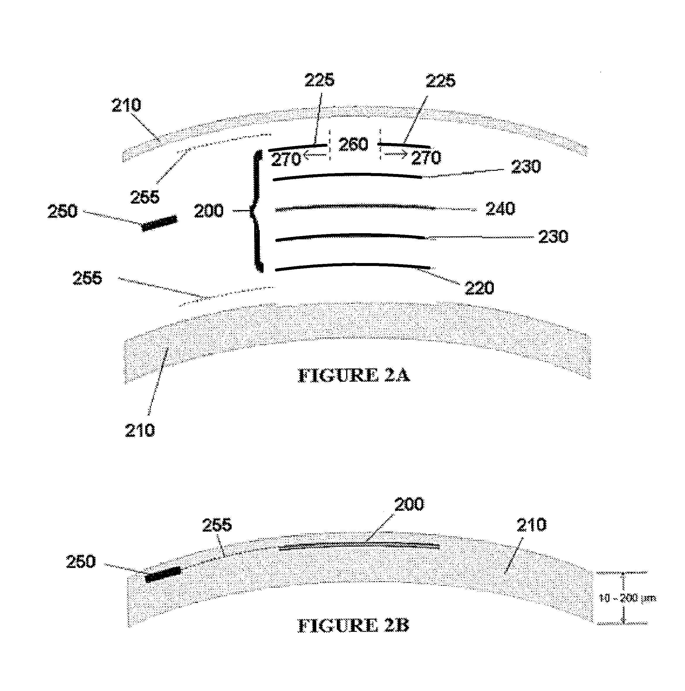
[0049]As used herein, an electro-active element refers to a device with an optical property that is alterable by the application of electrical energy. The alterable optical property may be, for example, optical power, focal length, diffraction efficiency, depth of field, optical transmittance, tinting, opacity, refractive index, chromatic dispersion, or a combination thereof. An electro-active element may be constructed from two substrates and an electro-active material disposed between the two substrates. The substrates may be shaped and sized to ensure that the electro-active material is contained within the substrates and cannot leak out. One or more electrodes may be disposed on each surface of the substrates that is in contact with the electro-active material. The electro-active element may include a power supply operably connected to a controller. The controller may be operably connected to the electrodes by way of electrical connections to apply one or more voltages to each o...


PUM


Abstract

Optical devices having a dynamic aperture and/or an apodization mask are provided. The aperture and/or mask may be provided by one or more electro-active elements, and may be used in an ophthalmic device that that is spaced apart from but in optical communication with an intraocular lens, a corneal inlay, a corneal onlay, or a spectacle lens that provide an optical power.

Description

CROSS-REFERENCES TO RELATED APPLICATIONS[0001]This application is a continuation in part of U.S. application Ser. No. 12 / 035,779, filed Feb. 22, 2008, which claims priority from U.S. Ser. No. 60 / 902,866 filed on Feb. 23, 2007, U.S. Ser. No. 61 / 020,759 filed on Jan. 14, 2008, U.S. Ser. No. 61 / 025,348 filed on Feb. 1, 2008, and U.S. Ser. No. 61 / 029,469 filed on Feb. 18, 2008, each of which is incorporated by reference in its entirety. This application claims the benefit of U.S. Ser. No. 61 / 037,351 filed on Mar. 18, 2008 and U.S. Ser. No. 61 / 060,291 filed on Jun. 10, 2008, each of which is incorporated by reference in its entirety.BACKGROUND OF THE INVENTION[0002]1. Field of the Invention[0003]The present invention relates to an intraocular optic, an intraocular lens, a corneal inlay, and a corneal onlay. More specifically, the present invention relates to an intraocular optic, an intraocular lens, a corneal inlay, and a corneal onlay having an apodization mask and / or a dynamic apertur...

Claims


Application Information

Patent Timeline
IPC IPC(8): A61F2/14G02C7/02G02F1/29G02C7/06G02F1/1333
CPCA61F2/14A61F2/16G02C7/101G02C7/08G02C7/083A61F2/1627A61F2/15A61F2/1613G02F1/294
Inventor BLUM, RONALD D.HADDOCK, JOSHUA N.KOKONASKI, WILLIAMGUPTA, AMITAVA
Owner EA3TECH LLC
Why Eureka
Try Eureka