
Insulated pipe and method for preparing the same

a technology of insulating pipes and pipes, which is applied in the field of preparing the same, can solve the problems of reducing the insulation efficiency of the insulating pipe, putting the performance of the assembly at risk, and reducing the amount of insulating materials required

Active Publication Date: 2009-08-20
CABOT CORP
View PDF43 Cites 23 Cited by
  • Summary
  • Abstract
  • Description
  • Claims
  • Application Information

AI Technical Summary

Benefits of technology

The invention provides a method and assembly for preparing an insulated pipe-in-pipe assembly. The method involves providing an assembly of inner and outer pipes, creating an annular space between the two pipes, and filling the space with a compressible material that is restrained within a container. The compressible material is then altered to increase its volume and form an insulated pipe-in-pipe-in-pipe assembly. The invention also provides an insulated pipe-in-pipe assembly comprising a porous, resilient, compressible material disposed in the annular space. Additionally, the invention provides an insulated pipe-in-pipe assembly comprising nanoporous silica in the annular space, which has low thermal conductivity and density.

Problems solved by technology

However, existing methods of insulating pipe-in-pipe assemblies remain deficient in numerous respects.
Pre-formed insulating panels and the like, of necessity retain gaps in insulation when placed within pipe-in-pipe assemblies, both between their opposing edges and between ends when laid end-to-end, allowing for heat transfer between inner and outer pipes, which reduces insulation efficiency and requires greater amounts of insulating materials.
Maintenance of reduced pressure within the annular space of some pipe-in-pipe assemblies places great demands on forming vacuum-tight assemblies and places the performance of the assembly at risk should the vacuum be compromised.
Some insulating materials such as polyurethane foam lose insulation efficiency and / or shape over service life.
Other insulating materials require the use of a larger diameter outer pipe to accommodate sufficient insulating material due to less efficient insulation capabilities.

Method used


Image

  • Insulated pipe and method for preparing the same
  • Insulated pipe and method for preparing the same
  • Insulated pipe and method for preparing the same

Examples


example

[0116]This example further illustrates the invention but, of course, should not be construed as in any way limiting its scope.

[0117]Four different amounts of silica aerogel particles were placed into a Plexiglas cell having an interior volume of 20×20×1 cm. In Sample A (control), the silica aerogel particles were disposed in the cell without any compression. In Samples B, C, and D (invention), increasing amounts of the silica aerogel particles were disposed in the cell with increasing amounts of compression to fit the silica aerogel particles within the interior volume of the cell.

[0118]For each sample, the percent compression was determined from the silica aerogel particle volume before compression (Vb) and the silica aerogel particle volume after compression (Va=working cell volume=400 cm3), i.e., the interior cell volume, using the following equation: Percent Compression=[(Vb-Va) / Vb]×100%. The bulk density of each sample was calculated by dividing the weight of the silica aerogel...


PUM

PropertyMeasurementUnit
particle sizeaaaaaaaaaa
pressureaaaaaaaaaa
thermal conductivityaaaaaaaaaa

Abstract

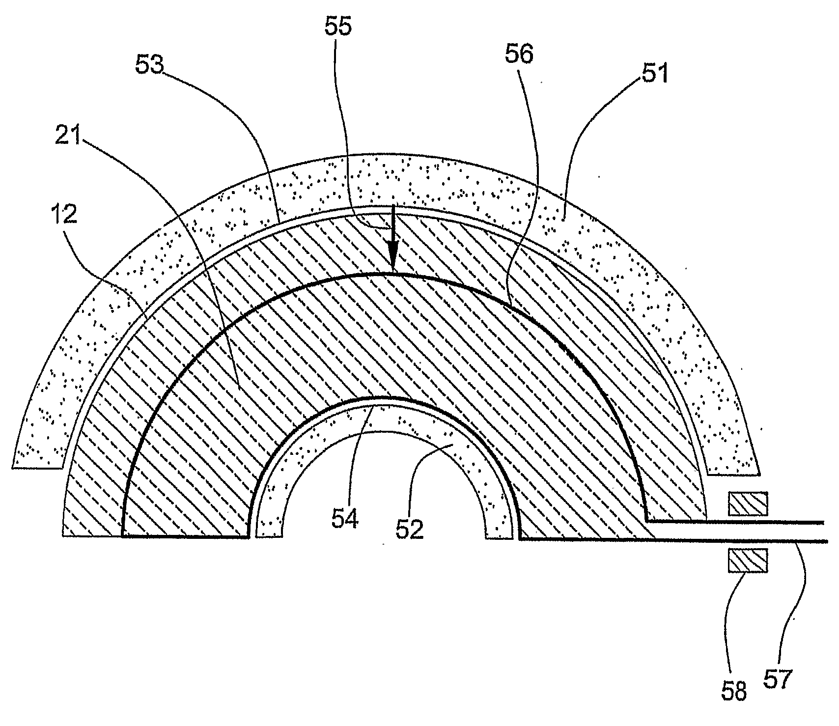
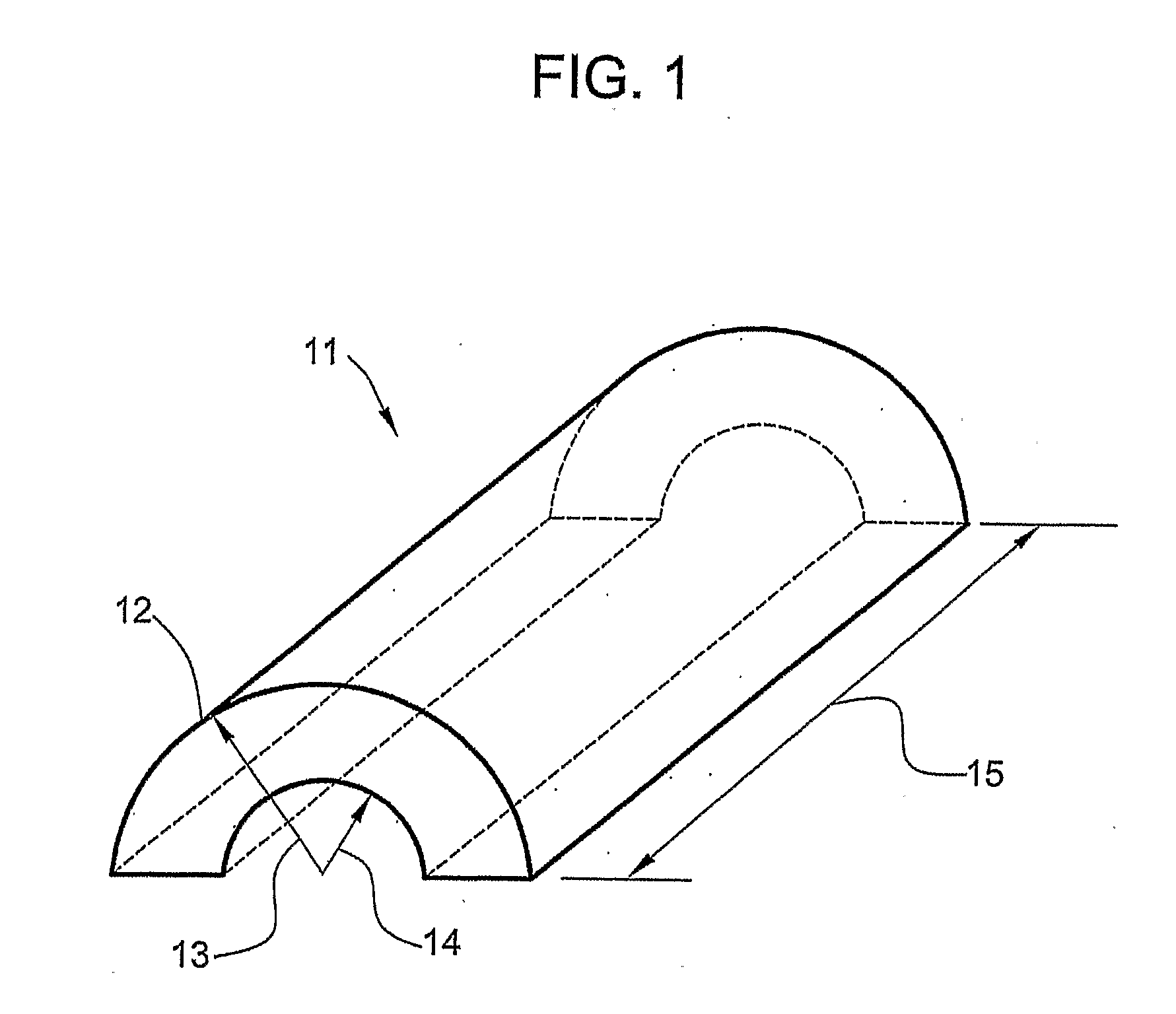
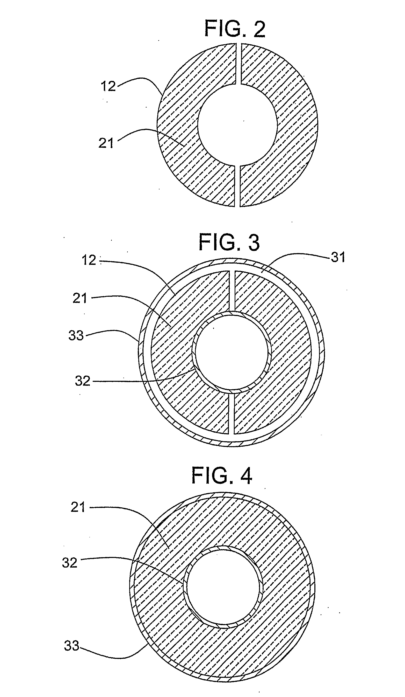
The invention provides an insulated pipe-in-pipe assembly comprising (a) at least one inner pipe, (b) an outer pipe disposed around the at least one inner pipe so as to create an annular space between the outer and inner pipes, (c) porous, resilient, compressible material disposed in the annular space, and (d) a remnant of a container that previously was positioned in the annular space and previously held the compressible material in a volume less than the volume of the compressible material in the annular space. The invention also provides a method for making such an insulated pipe-in-pipe assembly.

Description

PRIOR APPLICATIONS[0001]This application claims the priority of U.S. Provisional Application 60 / 687,672 filed on Jun. 6, 2005 and U.S. patent application Ser. No. 11 / 337,050 filed on Jan. 21, 2006.FIELD OF THE INVENTION[0002]This invention pertains to a thermally insulated pipe-in-pipe assembly and a method of preparing the same.BACKGROUND OF THE INVENTION[0003]In deep-water hydrocarbon (e.g. oil, gas or mixtures thereof) extraction, crude oil or gas is extracted from below the sea floor and transferred via a pipeline system to the surface of the water. It is critically important to maintain the temperature of the oil or gas flowing through the pipeline, which typically is extracted at elevated temperatures (e.g., 60-300° C.), at temperatures above about 40° C. to avoid the precipitation of solid materials and hydrates which can lead to plugging of the pipeline and interfere with production. As the water temperature at great depths is slightly above freezing temperature (e.g, about ...

Claims


Application Information

Patent Timeline
Patent Type & Authority Applications(United States)
IPC IPC(8): F16L9/14B23P11/00
CPCF16L59/143Y10T29/49826F16L59/153C04B30/00F16L59/028C04B38/08C04B14/064C04B14/06C04B38/0054F16L59/14F16L59/00
Inventor DINON, JOHN L.KALKSTEIN, HOBART C.MAITY, NIRMALYAPAINTAL, RAVIJITJOHNSON, AARON H.DU PLESSIS, ANDRIES
Owner CABOT CORP
Learn More