Compact diversity antenna system

a technology of diversity and antenna system, applied in the field of compact antenna system, can solve the problems of large number of precisely manufactured components, difficult to provide a compact antenna system, and high complexity of the antenna system

Active Publication Date: 2009-08-20
NETGEAR INC
View PDF19 Cites 342 Cited by
  • Summary
  • Abstract
  • Description
  • Claims
  • Application Information

AI Technical Summary

Benefits of technology

[0010]An object of the present invention is to provide a compact diversity antenna system. In accordance with an aspect of the present invention, there is provided a multiple antenna system comprising: a first antenna having two radiating bodies; a second antenna; and a passive element operatively coupled to the first antenna, the passive element configured as a Balun for the first antenna, the passive element configured to absorb and re-radiate electromagnetic radiation from the second antenna to produce a desired radiation pattern.

Problems solved by technology

However, due to other limitations, such as limited energy sources, regulations limiting the field strength of radio frequency activity, and limitations on energy flow in radio systems of compact size, such antenna systems are often highly complex if they are to achieve high bandwidth requirements of many radio systems.
This complexity often results in a large number of precisely manufactured components, making it challenging to provide an antenna system that is both compact and exhibits the performance required of modern radio systems.
An important factor affecting the performance of an antenna system is the tendency for radio communication to be degraded by undesirable interference.
Since these paths are of different lengths, electromagnetic radiation due to each path may exhibit destructive interference at the destination, a phenomenon known as multipath interference.
Traditional approaches to providing polarization and pattern diversity require antenna systems with multiple, independent antennas, which require additional space and detract from compactness.
This can pose a problem in designing an antenna system that simultaneously satisfies both compactness and performance requirements.
However, since only one mode can be used at a time, the diversity capability of this antenna system is limited.
However, as all antennas have the same polarization, this antenna system does not provide for polarization diversity.
However, standard techniques providing for polarization and pattern diversity may result in an unacceptably large or complex system of antenna elements.
Known antenna systems that attempt to provide for antenna diversity in a compact package have significant limitations with regard to antenna diversity.

Method used


Image

  • Compact diversity antenna system
  • Compact diversity antenna system
  • Compact diversity antenna system

Examples


example 1

[0060]The following examples are directed towards compact diversity antenna systems, and thus examples herein are directed toward compact design technology. In particular, these examples feature printed circuit board antenna designs, which are known in the art and are used for many applications as they are compact, economical, and easy to manufacture. It is obvious to a worker skilled in the art that other means, such as lengths of wire and coaxial cable, could also be used in construction of a multiple antenna system according to an embodiment of the present invention.

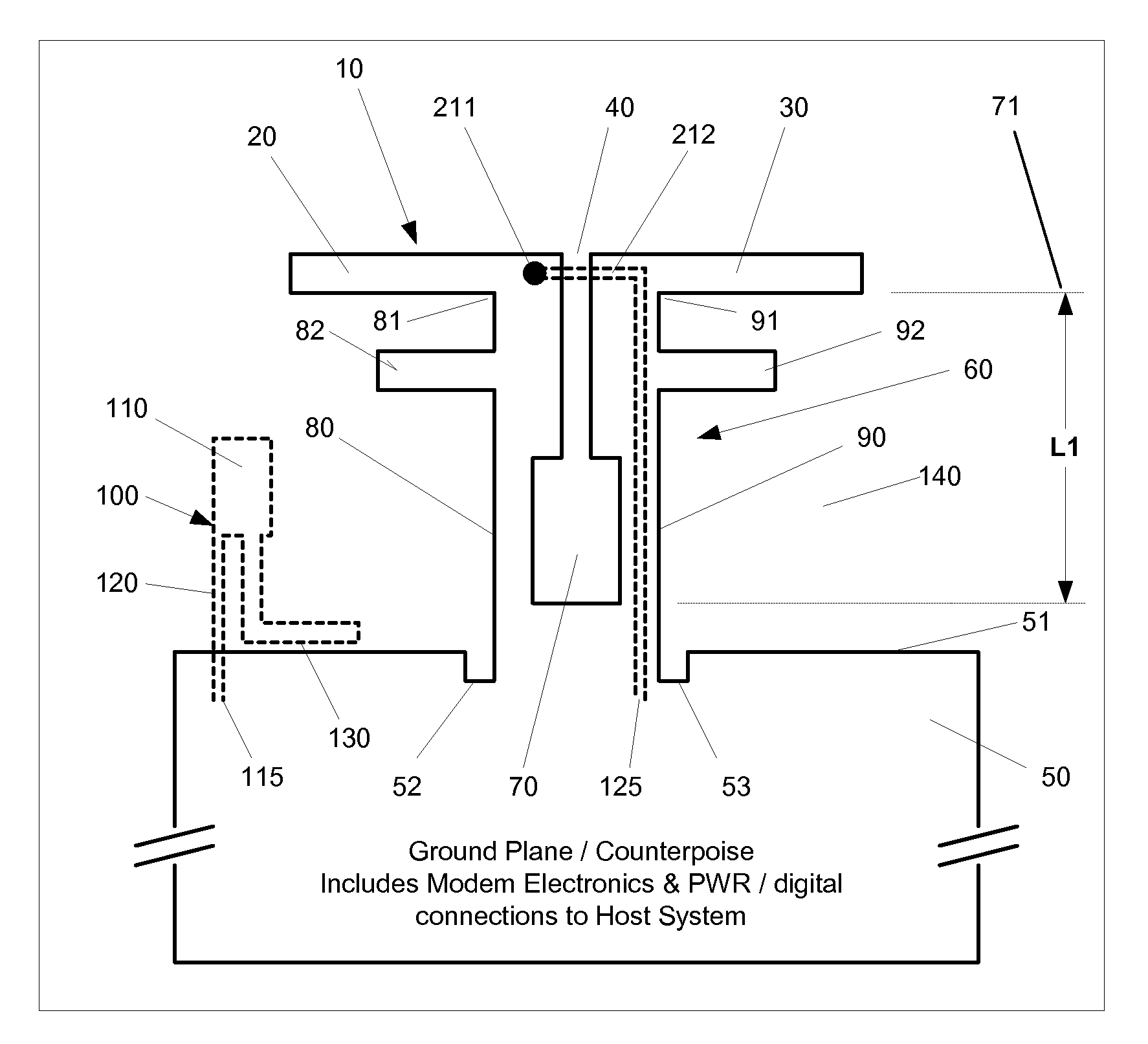
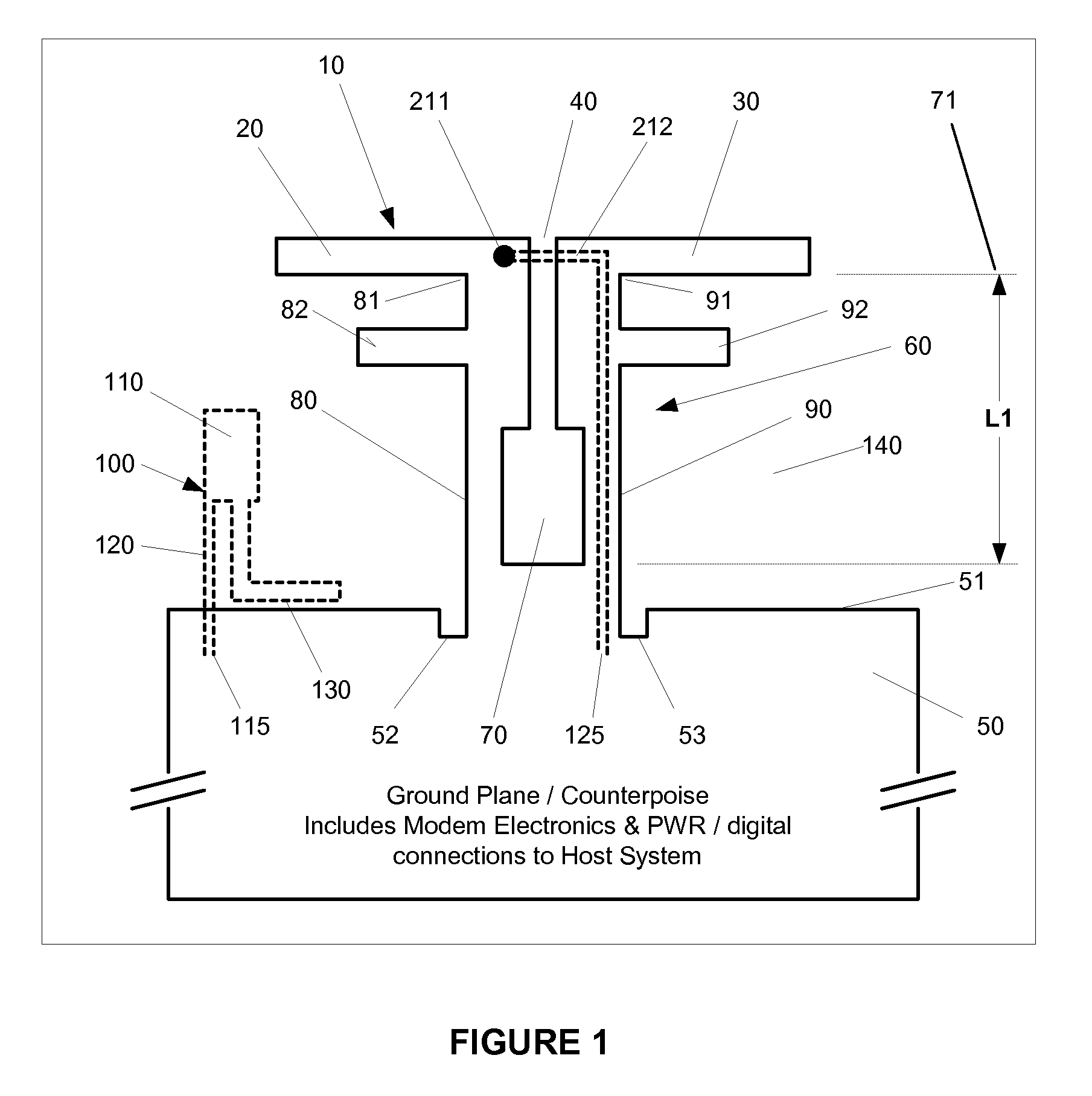
[0061]With reference to FIGS. 1 and 2, one embodiment of the present invention is illustrated having two antennas. FIG. 1 illustrates one layer of a printed circuit board having the following features comprising part of the present invention in accordance with Example 1. A first antenna 10 is depicted as a simple dipole comprising two radiating bodies 20 and 30, the radiating bodies separated by a gap 40. The first an...

example 2

[0065]FIG. 3 depicts two sides of a printed circuit board in a second example embodiment, being an extension to the embodiment of Example 1, wherein a second monopole antenna 320 is placed on the opposite side of the passive element 370 of the first monopole antenna 310. The second monopole antenna 320 operates analogously to the first monopole antenna 310 in Example 1, and comprises a radiating body 330, a series inductor 340 that connects from this body 330 to the transmission line 360, and shunt capacitor 350 coupling this second monopole antenna 330 to the ground plane 50. Second monopole antenna 320 is placed in a spaced-apart configuration with passive element 370, at a distance that allows passive element 370 to absorb and re-radiate electromagnetic radiation from second monopole antenna 320 to produce a desired radiation pattern. In particular, passive element 370 acts as a reflector as is known in the art, and also reduces the electromagnetic radiation seen by first monopol...

example 3

[0066]FIGS. 4 and 5 depict two sides of a printed circuit board in a third example embodiment, being an extension to the example embodiment of Example 2, wherein an additional dipole antenna 450 is provided extending, at substantially right angles at the 90 degree fold 485, out of the plane containing the antenna elements of Example 2: the first dipole antenna 410, passive element 420, second monopole antenna 430 and additional monopole antenna 440. This second dipole 450 is effectively orthogonal to all the other coplanar antennas. The additional dipole antenna 450 comprises a first radiating body 460, with top loading portion 461 added to allow for a reduction in length requirements, and a second radiating body 470. The second radiating body 470 further comprises a connecting portion 471, a first arm 472, and a second arm 473, defining a cavity 480. The ground plane 474 of the microstrip transmission line 477 is connected at a first end 491 to one radiating body of the first dipol...


PUM


Abstract

The present invention provides a compact antenna system having multiple antennas exhibiting polarization and pattern diversity. The system comprises at least two antennas which may have different polarizations, operatively coupled to a passive element which operates as a Balun for a first antenna and which is configured to absorb and re-radiate electromagnetic radiation from the second antenna to produce a desired radiation pattern. The present invention also provides for additional antennas operatively coupled to the passive element or to the first antenna to provide additional diversity.

Description

FIELD OF THE INVENTION[0001]The present invention pertains in general to antenna systems and in particular to compact antenna systems having multiple antennas.BACKGROUND[0002]In radio communications, compact antenna systems are desirable for reasons such as portability, cost, and ease of manufacture. Interest in compact antenna systems has been further stimulated by the use of higher radio frequencies, for example UHF and higher, which allow for antenna lengths significantly less than 1 centimetre, and by the development of lithographic techniques which allow for antenna systems to be printed directly onto circuit boards with small form factors at low cost. However, due to other limitations, such as limited energy sources, regulations limiting the field strength of radio frequency activity, and limitations on energy flow in radio systems of compact size, such antenna systems are often highly complex if they are to achieve high bandwidth requirements of many radio systems. This compl...

Claims


Application Information

Patent Timeline
Patent Type & Authority Applications(United States)
IPC IPC(8): H01Q9/04H01Q3/24H01Q21/00
CPCH01Q1/2275H01Q21/28H01Q9/30H01Q9/20H01Q5/40
Inventor NYSEN, PAULSCHULTEIS, GEOFF
Owner NETGEAR INC
Why Eureka
Try Eureka