Interactive image acquisition device

a technology of image acquisition and image, which is applied in the direction of direction finders, instruments, television systems, etc., can solve the problems of reducing resolution, long distance between the camera and the object, and it takes a lot of calculation to combine images taken by a plurality of cameras into an image seen from a certain viewpoint in real tim

Inactive Publication Date: 2009-08-20
UNIV OF ELECTRO COMM THE
View PDF5 Cites 66 Cited by
  • Summary
  • Abstract
  • Description
  • Claims
  • Application Information

AI Technical Summary

Benefits of technology

[0009]The present invention has been made in view of the above points and is intended to provide an interactive image acquisition device that can provide an image in real time in a way that gives a viewer a sense of reality by tracking a specified object.
[0016]According to the present invention, the connection image is generated by connecting the images captured by the image pickup elements that are arranged to take images of different directions. Based on the positional correlation between the target object specified from the connection image and the connection image, the target object can be placed substantially at the center of the connection image. That realizes a taken-image processing device and taken-image processing method that can provide an image in real time in a way that gives a viewer a sense of reality by tracking the specified object on the connection image.
[0017]Moreover, according to the present invention, with the driving electric power supplied from the power supply means, the device operates independently. The connection image is generated by connecting the images captured by the image pickup elements that are arranged to take images of different directions. Based on the positional correlation between the target object specified from the connection image and the connection image, the target object can be placed substantially at the center of the connection image. That realizes a taken-image processing device that can provide an image in real time in a way that gives a viewer a sense of reality by tracking the specified object on the connection image.
[0018]Furthermore, according to the present invention, the device is placed at a predetermined place to be observed. The connection image depicting that place is generated by connecting the images captured by the image pickup elements that are arranged to take images of different directions. Based on the positional correlation between the target object (which exists in an area to be observed) specified from the connection image and the connection image, the target object can be placed substantially at the center of the connection image. That realizes a taken-image processing device that can provide an image in real time in a way that gives a viewer a sense of reality by tracking the specified object on the connection image depicting that place.

Problems solved by technology

But all the methods use fixed cameras and the distance between the camera and the object can be long.
This could lead to reduction in resolution.
Moreover, it takes enormous calculation to combine images taken by a plurality of cameras into an image seen from a certain viewpoint in real time.
Although omnidirectional images can be acquired at each location, technique for stabilizing cameras in order to prevent blurring of images due to moving objects' movement and how to disperse cameras have not been studied yet.
However, when many fixed cameras are placed in a stadium to produce an image seen from a certain viewpoint, the distance between a fixed camera and an object can be very long, leading to reduction in resolution.
This cannot provide a viewer with an image that presents a sense of reality as if it tracks his / her desired object near the object.

Method used


Image

  • Interactive image acquisition device
  • Interactive image acquisition device
  • Interactive image acquisition device

Examples


first embodiment

(2) First Embodiment

(2-1) Overall Configuration of Indoor Situation Surveillance System According to First Embodiment

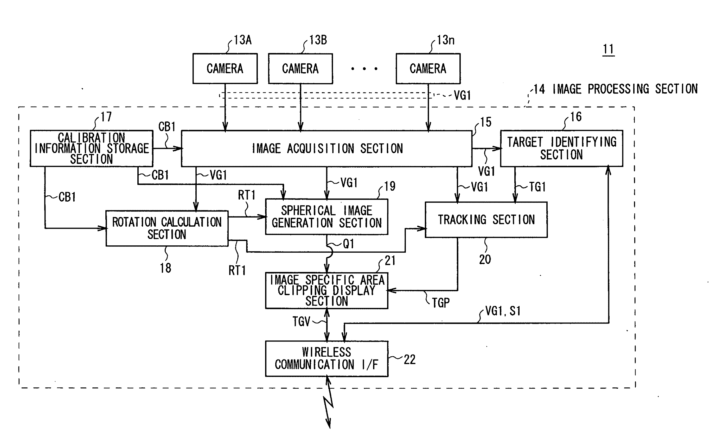
[0058]In FIG. 5, the reference numeral 10 denotes an indoor situation surveillance system according to a first embodiment of the present invention. The indoor situation surveillance system 10 includes an indoor situation confirmation ball 11 (which is the equivalent of the object-surface-dispersed camera 1 (FIG. 1)) that takes omnidirectional images and combines them to create the spherical image Q1 (FIGS. 3 and 4); and a notebook-type personal computer (also referred to as a “note PC”) 12, which wirelessly receives the spherical image Q1 and displays it.

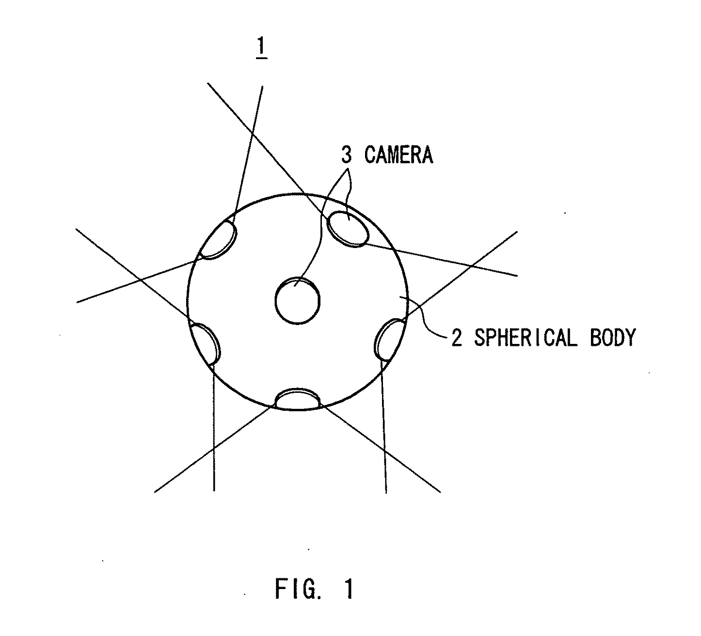
[0059]The indoor situation confirmation ball 11 has n cameras 13 on its spherical body 11A's surface so that the cameras 13 can take omnidirectional images (a plurality of images in different directions). The positional correlation for connecting images has been calibrated.

[0060]By the way, the indoor situation confir...

second embodiment

(3) Second Embodiment

(3-1) Overall Configuration of Capsule Endoscope System of Second Embodiment

[0139]In FIG. 17 whose parts have been designated by the same reference numerals and symbols as the corresponding parts of FIG. 5, the reference numeral 50 denotes a capsule endoscope system according to a second embodiment of the present invention. The capsule endoscope system 50 includes a capsule endoscope 51, which is the equivalent of the object-surface-dispersed camera 1 (FIG. 1); and the note PC 12, which wirelessly receives and displays a spherical image Q1 generated by the capsule endoscope 51 that takes omnidirectional images (or a plurality of images in different directions) inside a person's body.

[0140]The capsule endoscope 51 includes the n cameras 13 placed on the surface of a spherical body 53 covered by a transparent cover 52 at the tip of the capsule. The cameras 13 are arranged to take omnidirectional images (or a plurality of images in different directions) inside a pe...

third embodiment

(4) Third Embodiment

(4-1) Overall Configuration of Security System of Third Embodiment

[0187]In FIG. 20 whose parts have been designated by the same reference numerals and symbols as the corresponding parts of FIG. 5, the reference numeral 70 denotes a security system according to a third embodiment of the present invention. The security system 70 includes a surveillance camera 71, which is the equivalent of the object-surface-dispersed camera 1 (FIG. 1) and is attached to a ceiling; and a personal computer 75, which wirelessly receives a hemispherical image Q2 from the surveillance camera 71 that includes the n cameras 72A to 72n on its hemispherical body. The n cameras 72A to 72n for example take omnidirectional images inside an ATM room 73 at a bank and combine them to generate the hemispherical image Q2.

[0188]The surveillance camera 71 includes the n cameras 72A to 72n placed on the surface of the hemispherical body. The cameras 72A to 72n are arranged and calibrated to take omni...


PUM


Abstract

The present invention tracks a specified target object and provides an image in real time in a way that gives a viewer a sense of reality. The present invention connects, in order to produce a spherical image Q1, the images captured by cameras 13 that can move in a space and are arranged so as to take images of different directions such that the images captured by at least two or more image pickup elements are partially overlapped with one another, calculates a positional correlation between the spherical image Q1 and the target object specified from the images, and then arranges the target object substantially at the center of the spherical image Q1 in accordance with the positional correlation. This provides a tracking image that tracks and focuses on the target object out of the spherical image Q1.

Description

TECHNICAL FIELD[0001]The present invention relates to an interactive image acquisition device, and is preferably applied for a tracking display, in which a desired object is tracked from images taken by an omnidirectional camera placed over the surface of a spherical body, for example.BACKGROUND ART[0002]At present, many cameras are spread in our living space such as a station or a street corner. In addition, camera-attached cell phones and the like have become popular. Those devices help constitute a “ubiquitous” space in our society. However, many of those cameras are fixed on particular positions in a space for fixed-point surveillance.[0003]It is a common practice in academic field that a plurality of cameras whose positions are already known are connected each other via a network and the images taken by the cameras are analyzed to track a particular object. Particularly, the Carnegie Mellon University is trying to create an image seen from a certain viewpoint by using many fixe...

Claims


Application Information

Patent Timeline
Patent Type & Authority Applications(United States)
IPC IPC(8): H04N7/18G06K9/00
CPCG01S3/7864G08B13/19641H04N5/232H04N5/23238H04N2005/2255H04N5/2628H04N5/76H04N7/181H04N5/247H04N23/555H04N23/698H04N23/90
Inventor INAMI, MASAHIKOSEKIGUCHI, DAIROKUMORI, HIROKIKUWASHIMA, SHIGESUMIMATSUNO, FUMITOSHI
Owner UNIV OF ELECTRO COMM THE
Why Eureka
Try Eureka