Holographic display devices

a technology of optical systems and display devices, applied in the field of optical systems for holographic projectors, can solve problems such as inability to achiev

Inactive Publication Date: 2009-08-20
LIGHT BLUE OPTICS
View PDF5 Cites 38 Cited by
  • Summary
  • Abstract
  • Description
  • Claims
  • Application Information

AI Technical Summary

Benefits of technology

The present technology relates to displaying images through a hologram system. By encoding a lens within the hologram, it becomes possible to change its power and thus vary the size of the display image. This allows for greater flexibility and precision when controlling the image's appearance. Additionally, the use of a Fresnel hologram eliminates the requirement for a separate conjugate image, resulting in sharper and clearer displays at various viewing distances.

Problems solved by technology

The technical problem addressed by this patent is how to enable smaller electronics devices with screens to show bigger or projected images without requiring an oversized optical system. This issue arises due to limitations related to the device's size. Using a holographic projector may offer a possibility to solve this challenge in a limited area.

Method used


Image

  • Holographic display devices
  • Holographic display devices
  • Holographic display devices

Examples


Embodiment Construction

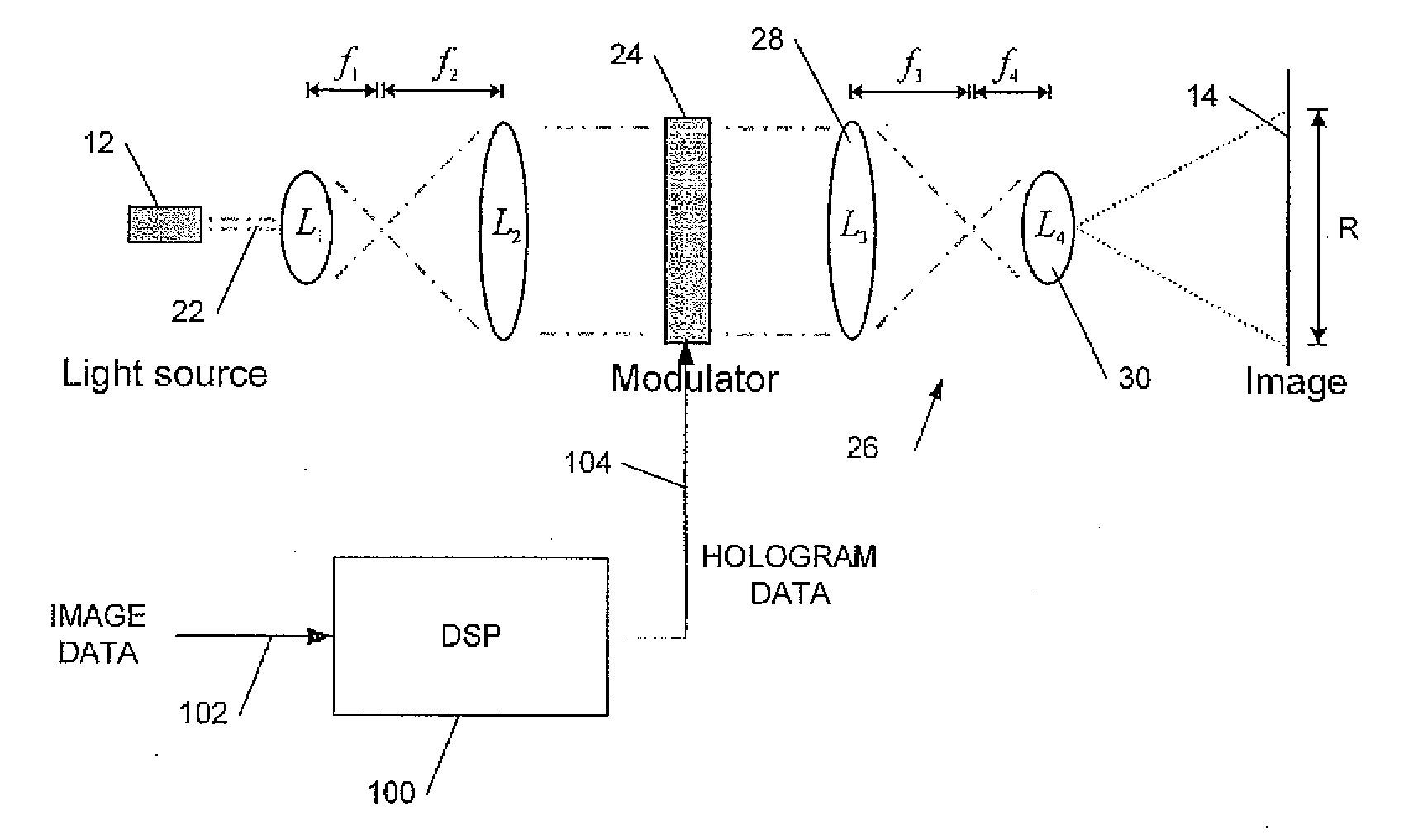
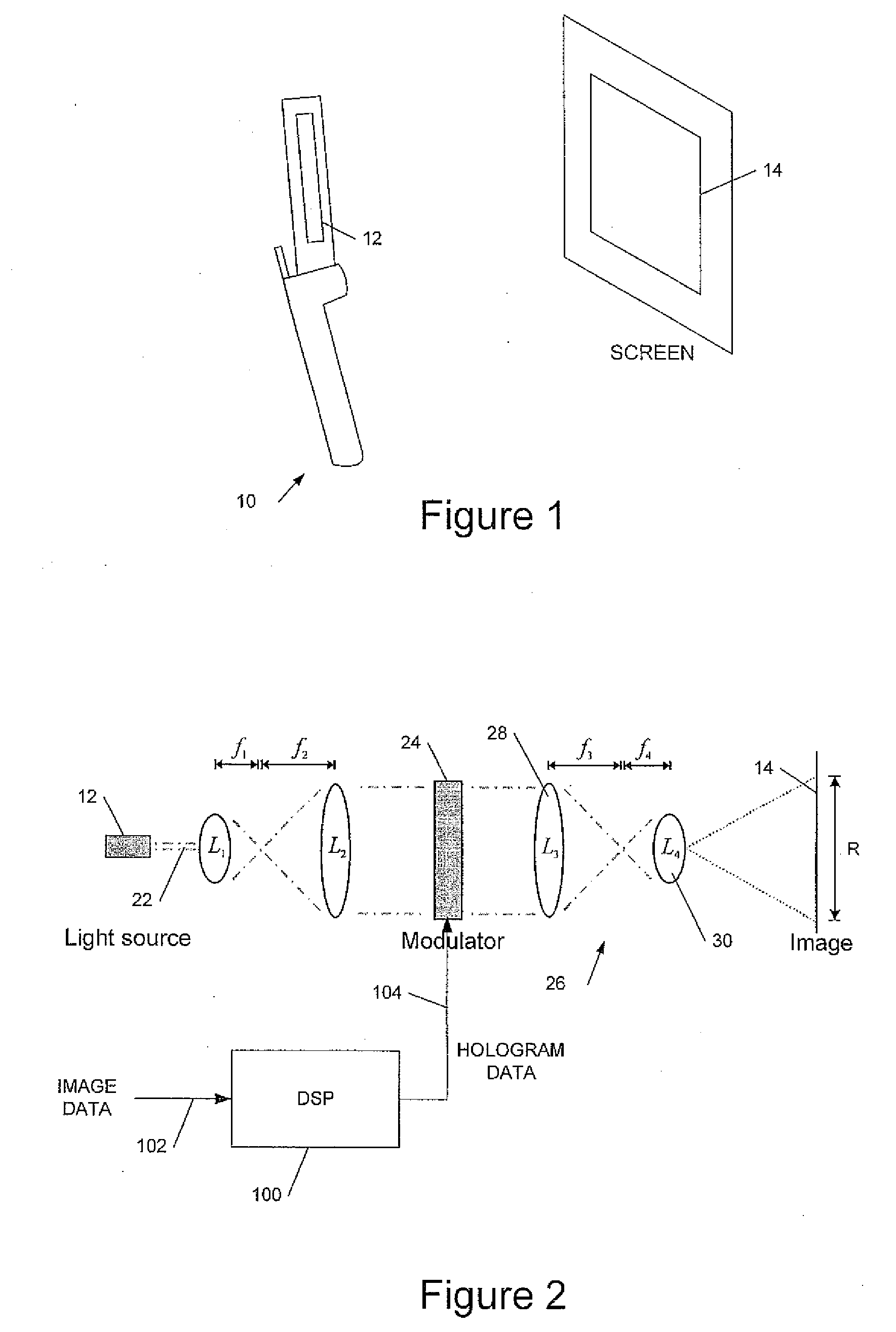
[0032]We have previously described, in UK patent application number 0512179.3 filed 15 Jun. 2005, incorporated by reference, a holographic projection module comprising a substantially monochromatic light source such as a laser diode; a spatial light modulator (SLM) to (phase) modulate the light to provide a hologram for generating a displayed image; and a demagnifying optical system to increase the divergence of the modulated light to form the displayed image. Absent the demagnifying optics the size (and distance from the SLM) of a displayed image depends on the pixel size of the SLM, smaller pixels diffracting the light more to produce a larger image. Typically an image would need to be viewed at a distance of several metres or more. The demagnifying optics increase the diffraction, thus allowing an image of a useful size to be displayed at a practical distance. Moreover the displayed image is substantially focus-free: that is the image is substantially in focus over a wide range o...


PUM


Abstract

This invention relates to optical systems for holographic projectors. We describe a holographic image projection system, the system including: a spatial light modulator (SLM) for displaying a hologram; first optics to provide an input beam to said SLM; second optics to process an output beam from said SLM to provide a displayed image; and a hologram processor to receive image data for display and to output data to said SLM to display a hologram to provide said displayed image; and wherein at least one lens of said first optics or said second optics is encoded in said hologram.

Description


Claims


Application Information

Patent Timeline
Owner LIGHT BLUE OPTICS
Why Eureka
Try Eureka