Low-profile wheel chock assembly

a low-profile, wheel technology, applied in the direction of transportation and packaging, transportation items, items transportation vehicles, etc., can solve the problems of difficult to chock a wheel, lack of clearance, and inability to afford manual installation clearance, so as to enhance the rigidity of the monolithic body and effectively prestress the body

a low-profile, wheel technology, applied in the direction of transportation and packaging, transportation items, items transportation vehicles, etc., can solve the problems of difficult to chock a wheel, lack of clearance, and inability to afford manual installation clearance, so as to enhance the rigidity of the monolithic body and effectively prestress the body

US20090208304A1Active Publication Date: 2009-08-20GE GLOBAL SOURCING LLC

Image

  • Low-profile wheel chock assembly
  • Low-profile wheel chock assembly
  • Low-profile wheel chock assembly

Examples


Embodiment Construction

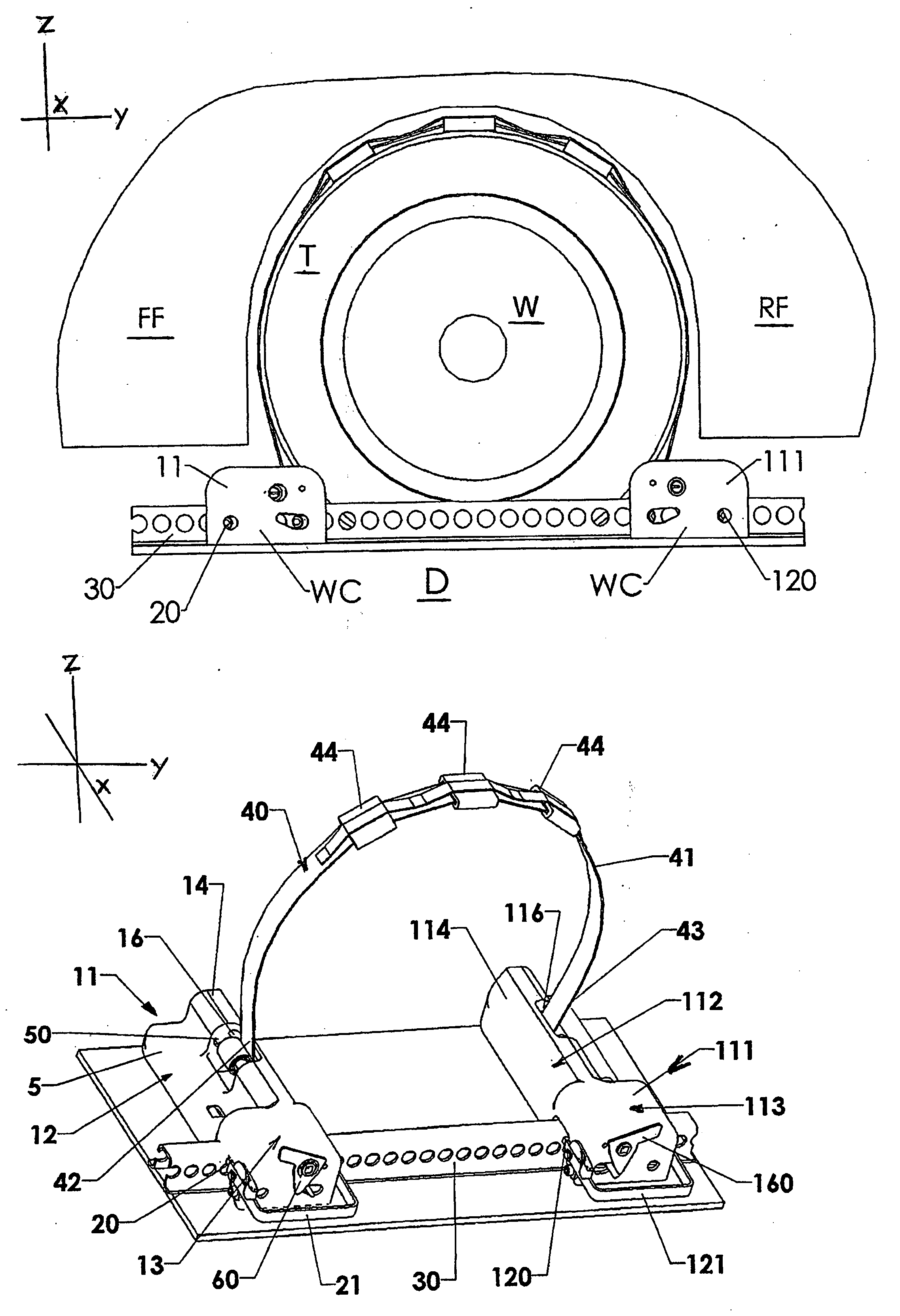
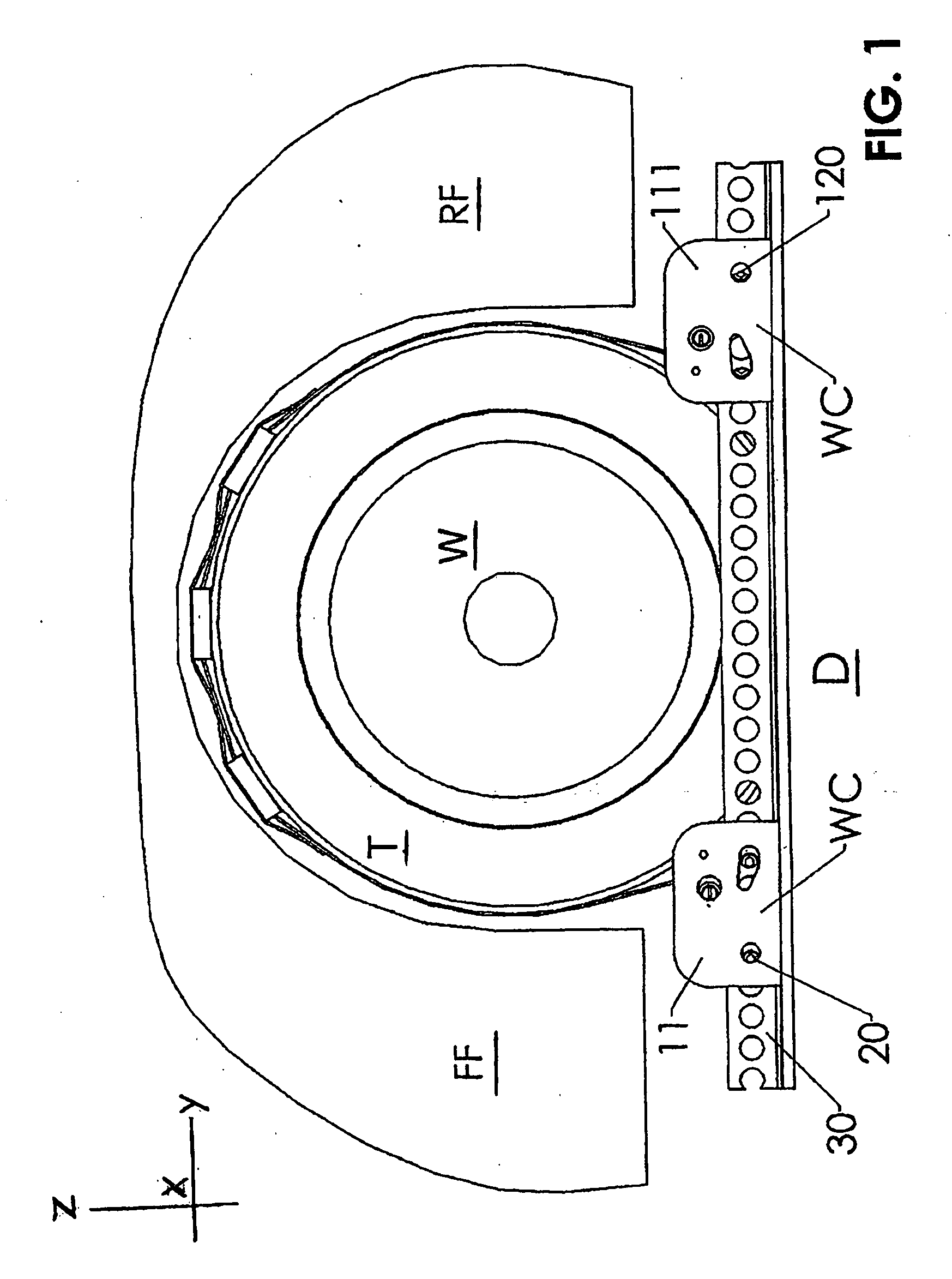
[0046]Referring to the drawings, and particularly to FIGS. 1 and 2, there is shown a “low-drag” fender having front and rear portions FF and RF respectively defining a wheel-well in which a wheel W is located. As is evident, the periphery of the fender is adjacent the periphery of the tread of the tire leaving a clearance of less than 6.35 cm (2.5″). The lower edge of the fender, above deck D on which the wheel rests, is less than 15.0 cm (5.9″) above the deck D.

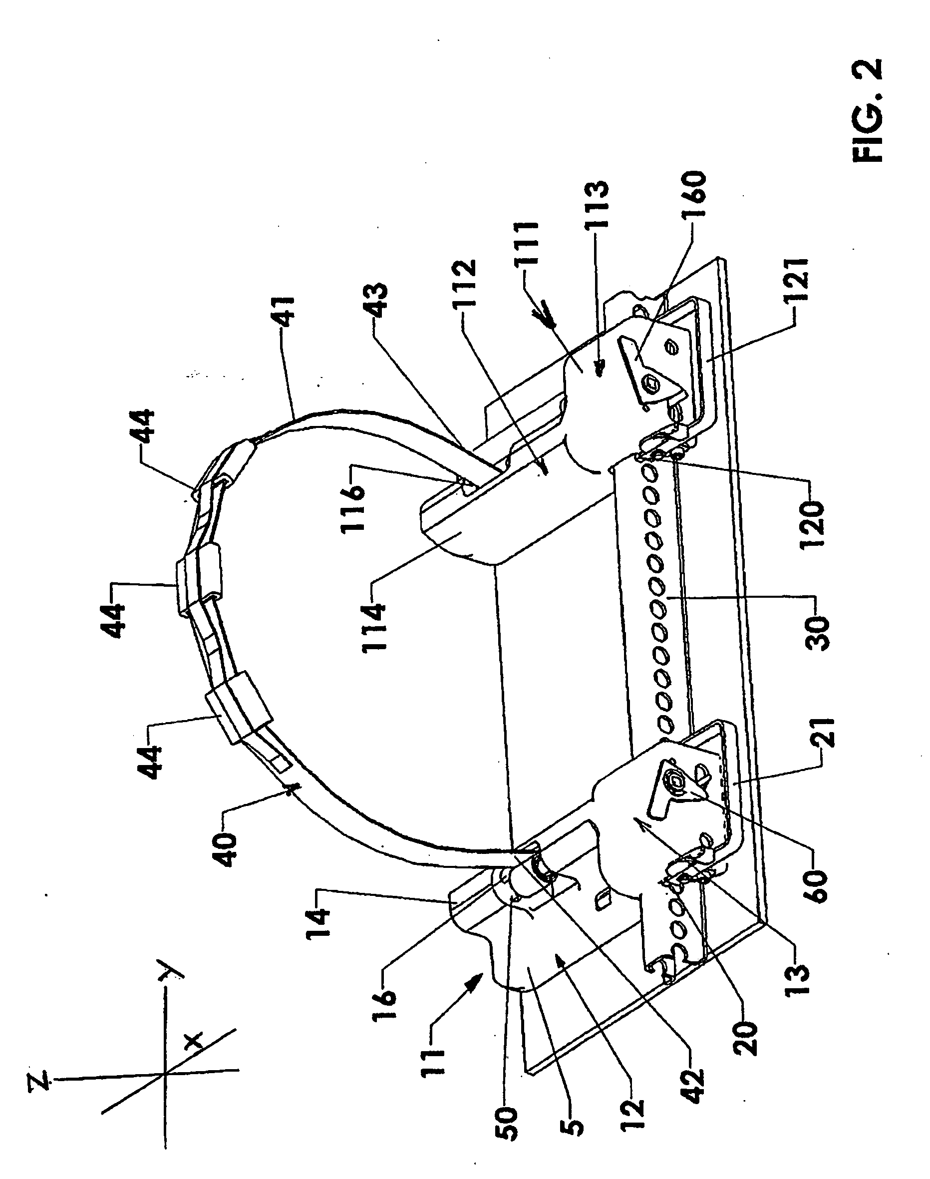
[0047]A wheel chock assembly, indicated generally by WC, includes a pair of first (front) and second (rear) active chocks, indicated generally by reference numerals 11 and 111 respectively, as they would be positioned beneath a car, chocking a tire T between them. Each chock 11 and 111 is locked with first and second locking means 20 and 120 respectively, to a chock-rail 30 fixed to the deck D, each chock in a location chosen so as to contact and snugly restrain the tire T between them. The heads of pins 71, 72 (see FIG. 7) ...


PUM


Abstract

A low elevational profile of each of a pair of first and second wheel chocks for restraining a current “low-drag” motor vehicle in a carrier, such as a railway car, is derived from each wheel chock having an internally webbed, elongated stepped-box body terminated with a relatively short rectangular box having its inner wall integrally formed with the stepped-box body. The body of the first chock is essentially a mirror-image of the second chock body. The low profile of a wheel chock allows each to be positioned under a vehicle the rocker panel of which has its lower edge only 148 mm (5.82 inches) above the surface upon which the vehicle's tire rests, so that the installed chock height is reduced to 47.6 mm (1.87″) under the components of the vehicle's body. The assembly may include a pair of “active” chocks; or, one active chock and one anchor chock. A single window in the upper portion of the stepped-box provides access for a strap of a wheel harness, which strap is wrapped around a torque tube in an active chock. The torque tube in one chock is rotatable in a direction opposite to that of the torque tube of the other chock. With a pair of active chocks, hooks on straps of a prior art harness are eliminated because it is difficult and time-consuming to manipulate a tire harness with its straps and hooks to secure the tire between the wheel chocks. When one chock is an anchor chock, one end of the strap is provided with a hook which is anchored to a rod or tube which is substituted for the rotatable torque tube.

Description

FIELD OF THE INVENTION[0001]This invention relates to a wheel chock assembly which secures a vehicle in a carrier or transporter in which the vehicle is transported. The wheel chock includes a wheel harness to restrain the vehicle by securing its wheels to the floor of the carrier. A typical carrier is a railway car or a ship. Each wheel chock of the assembly is specifically designed and constructed for installation on a rail, one chock positioned in front of a vehicle's wheel and the other chock behind the wheel. As used herein, the term “wheel” refers to the combination of a wheel rim and a tire mounted thereon. The goal is to restrain a current “low-drag” automobile adequately without damaging components in its wheel-well despite the clearance between the automobiles fenders and rocker panels being restricted by the requirements of “low drag”.BACKGROUND OF THE INVENTION[0002]Wheel chocks for restraining the movement of a motor vehicle in a carrier such as railroad cars are well k...

Claims


Application Information

Patent Timeline
20 Aug 2009
Publication
US20090208304A1
IPC
B61D3/18
CPC
B60P3/075; B60P3/079; B60P3/077
Inventors
BULLOCK, ROBERT LEE