Implant planning using corrected captured joint motion information

Active Publication Date: 2009-08-20
MAKO SURGICAL CORP
View PDF61 Cites 335 Cited by
  • Summary
  • Abstract
  • Description
  • Claims
  • Application Information

AI Technical Summary

Benefits of technology

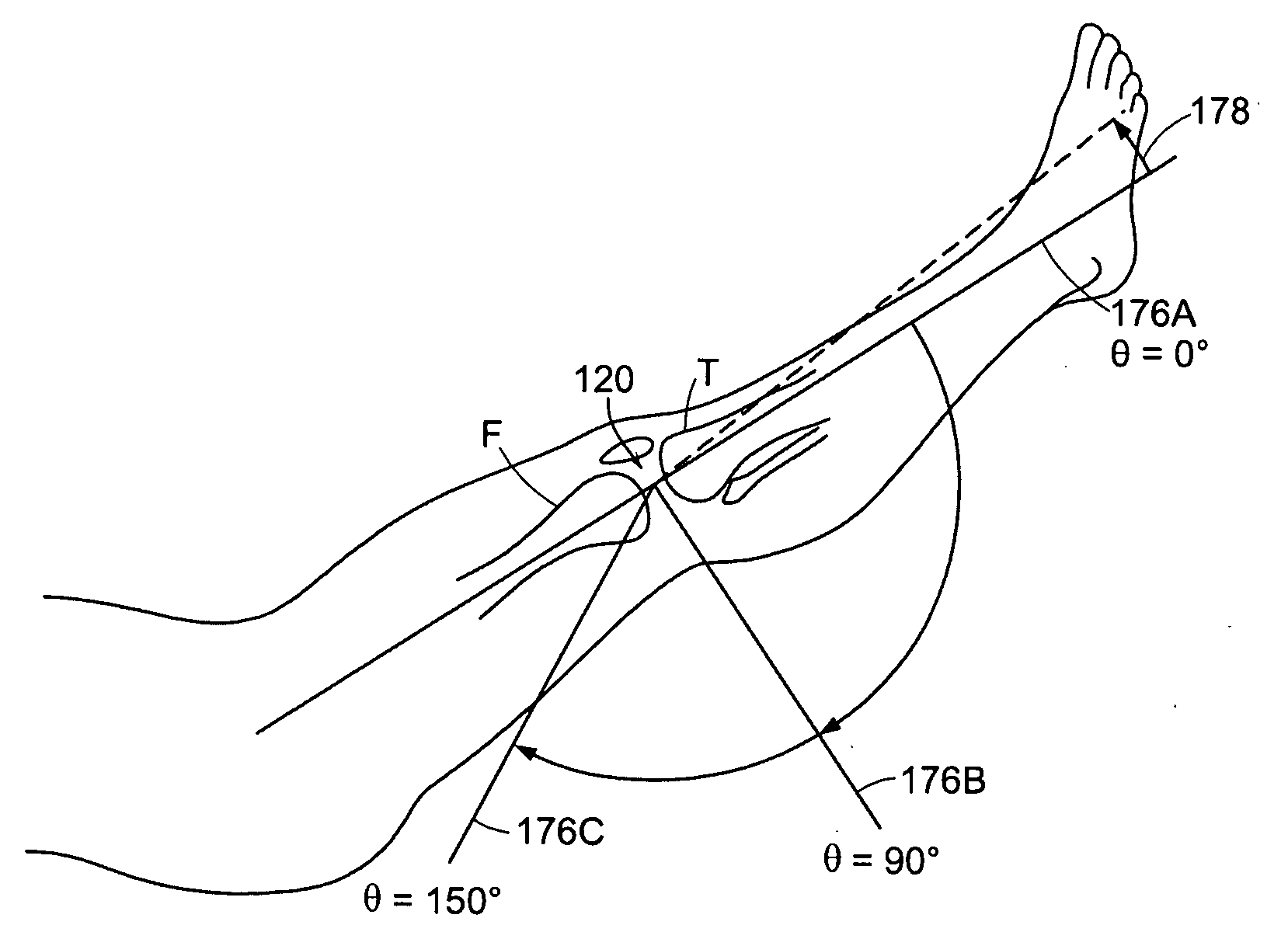
[0015]In some examples, at least one point is mapped on a surface of the first implant model at a plurality of poses within the range of motion of the joint, inclusive, and at least one of the mapped points is aligned with the second implant model. A user can be enabled to change a pose of at least one of the first implant model and the second implant model to preserve a distance between the first implant model and the second implant model through at least a portion of the range of motion of the joint. A pose of at least one of the first implant model and the second implant model can be adjusted to achieve a desired relationship between the first implant model and the second implant model through at least a portion of the corrected range of motion of the joint.
[0018]Advantageously, implant positions can be planned using preoperative CT-derived models of a joint subject to a disease pathology by intraoperatively neutralizing defects caused by the disease pathology, applying a corrective force to align the bones of the limb to achieve a corrected pose (i.e., a desired limb alignment concurrent with appropriate ligament tension), capturing relative bone pose data with the limb in the corrected pose, and planning implant placement based on the captured bone pose data and preoperative CT-derived models. As a result, implant planning and bone cutting can be accomplished such that when the implants are installed, the postoperative result is a joint that can achieve the desired limb alignment with appropriate ligament tension throughout the range of motion of the joint.

Problems solved by technology

Inaccurate positioning of implants may compromise joint performance and reduce implant life.
Anatomical variation complicates implant planning because there is no single implant design or placement of implant components that provides an optimal solution for all patients.
Implant planning is further complicated when the joint is subject to a disease state, such as osteoarthritis, that causes defects (e.g., osteophytes, capsular adhesions, osteochondral defects (OCD), and the like) that prevent the bones of the limb from achieving a desired alignment, such as a neutral alignment.
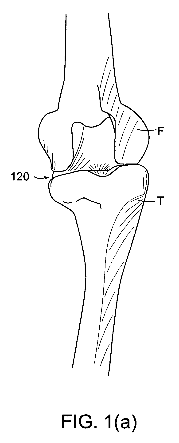
In contrast, when a person has disease in one compartment of the knee joint (e.g., medial or lateral), the diseased compartment may collapse, causing the limb to adopt a non-neutral or misaligned pose.
Because the disease state may prevent the limb from achieving the desired pose, however, the preoperative images may not enable the surgeon to accurately assess how the femur and tibia would move relative to one another in the desired alignment.
As a result, the surgeon may have difficulty determining how to place and orient each implant component to postoperatively achieve the desired limb alignment throughout the range of motion of the joint.

Method used


Image

  • Implant planning using corrected captured joint motion information
  • Implant planning using corrected captured joint motion information
  • Implant planning using corrected captured joint motion information

Examples


Embodiment Construction

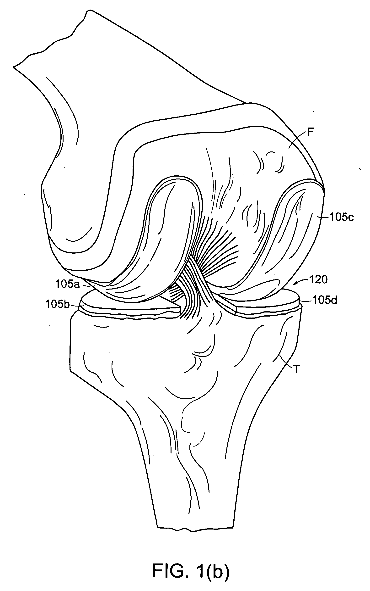
[0051]Presently preferred embodiments are illustrated in the drawings. Although this specification refers primarily to unicondylar knee joint replacement surgery, it should be understood that the subject matter described herein is applicable to other joints in the body, such as, for example, a shoulder, elbow, wrist, spine, hip, or ankle and to any other orthopedic and / or musculoskeletal implant, including implants of conventional materials and more exotic implants, such as orthobiologics, drug delivery implants, and cell delivery implants. While some figures and associated descriptions refer primarily to medial unicompartmental knee arthroplasty (UKA), this is for description purposes only and is in no way intended to be limiting.

[0052]As used herein the term “pose” refers to position and / or orientation and includes, for example, defining three degrees of freedom (DOF) of position and / or three degrees of freedom of orientation (i.e., up to six DOF total) of an object. Pose can refe...


PUM


Abstract

The description relates to surgical computer systems, including computer program products, and methods for implant planning using corrected captured joint motion information. Data representative of a corrected limb pose at a plurality of poses within a range of motion of a joint associated with a particular individual is captured, the joint comprising a first bone and a second bone, while the first bone, the second bone, or both are subject to a corrective force aligning the first and second bones in a desired alignment. The first bone of the joint is represented. The second bone of the joint is represented. A first implant model is associated with the representation of the first bone. A second implant model is associated with the representation of the second bone. Based on the captured data, a relationship is determined between the first implant model and the second implant model at one or more poses of the plurality of poses within the range of motion of the joint. Information representative of the determined relationship is displayed.

Description

CROSS REFERENCE TO RELATED APPLICATIONS[0001]The present application claims priority to U.S. Provisional Patent Application Ser. No. 61 / 066,389, filed on Feb. 20, 2008, entitled “Valgus moment method,” which is hereby incorporated by reference herein in its entirety.FIELD OF THE INVENTION[0002]The invention relates to surgical computer systems, including computer program products, and methods for implant planning using corrected captured joint motion information.BACKGROUND OF THE INVENTION[0003]Orthopedic joint replacement surgery may involve arthroplasty of a knee, hip, or other joint (e.g., shoulder, elbow, wrist, ankle, finger, etc.). During joint replacement surgery, a surgeon typically removes diseased bone from the joint and replaces the resected bone with prosthetic implant components. Challenges of joint replacement surgery include determining the appropriate position for implant components within the joint relative to the bone and other implant components and accurately cut...

Claims


Application Information

Patent Timeline
IPC IPC(8): A61B5/103
CPCA61B19/50A61B19/56A61B2019/461A61F2/38A61B2019/507A61B2019/5268A61B2019/501A61B34/10A61B34/25A61B2034/101A61B2034/107A61B2034/2068A61B2090/061G16H20/40G16H50/50
Inventor VAN VORHIS, ROBERTBLACKWELL, TIMOTHY
Owner MAKO SURGICAL CORP
Why Eureka
Try Eureka