Roofing bracket and system

a technology for roofs and brackets, applied in the direction of roofs, buildings, doors/windows, etc., can solve the problems of cumbersome and expensive process, more challenging and time-consuming aspects, and increase the cost of construction

Inactive Publication Date: 2009-08-27
GP INNOVATIVE CONCEPTS
View PDF27 Cites 44 Cited by
  • Summary
  • Abstract
  • Description
  • Claims
  • Application Information

AI Technical Summary

Problems solved by technology

This process is cumbersome and expensive, as special equipment located off the job site is often necessary to fabricate the purlins to the desired angle.
Rotating and fastening the bracket to the post and purlin is considered one of the more challenging and time consuming aspects to such an installation.

Method used


Image

  • Roofing bracket and system
  • Roofing bracket and system
  • Roofing bracket and system

Examples


first embodiment

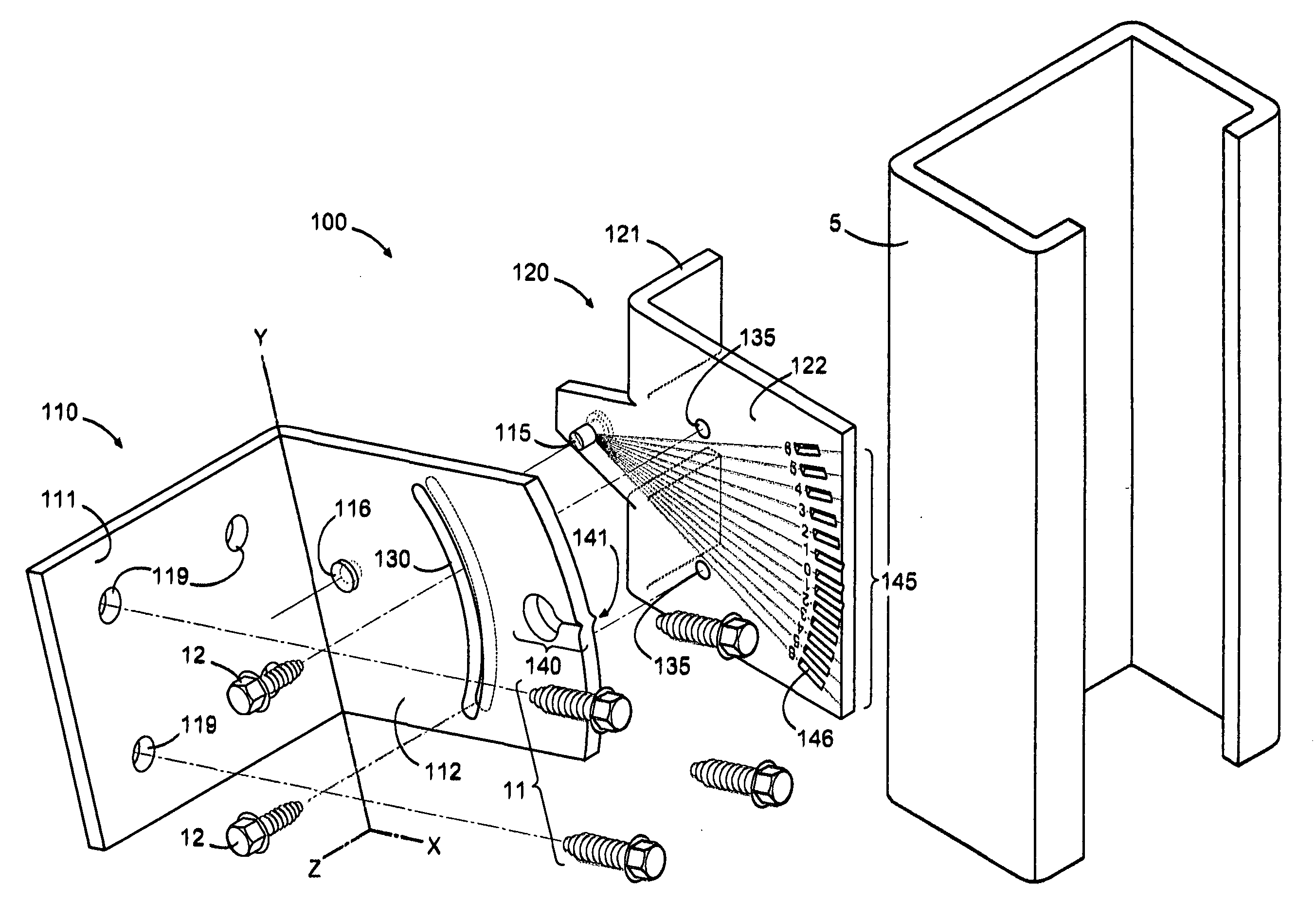
[0031]FIG. 3A is an exploded perspective view of a roofing bracket 100. Bracket 100 is comprised of two pieces, a clip 110 and a brace 120, coupled together with a rivet 115. The rivet forms a pivot point from which the two pieces (110 and 120) can be rotated about each other.

[0032]The clip 110 is comprised of two faces that meet at a common edge, forming a 90° angle. A first face 111 is designed to attach to the purlin 15 of the roofing system 1 (see FIGS. 1-2). The second face 112 is designed to attach to the vertical post 5, thus creating the coupling of the purlin 15 to the post 5.

[0033]The first face 111 may include preformed holes 119 for receiving fasteners 11. The first face 111 would preferably mount flush to the vertical face of a “Z” purlin and fastened thereto with fasteners 11. The specific location of the network of preformed holes 119 is beyond the scope of the present invention. Alternatively, no holes may be preformed in the face 111. The specific dimensions of the ...

second embodiment

[0043]FIG. 4A-B illustrate a roofing bracket 200 according to the present invention. Similar to the roofing bracket 100 of FIGS. 3A-B, roofing bracket 200 comprises two pieces: a clip 210 and brace 220. Two variations are provides to distinguish this embodiment from the previous embodiment.

[0044]First, the preformed radial slit 130 of the clip 110 is replaced with stamped radial guides 231. In this case, the slit is not actually cut and removed from the metal. In this embodiment, self-puncturing fasteners would be required.

[0045]Second, the pivot point, and thus rivet 215 and rivet hole 216 has been positioned in the lower left corner, as opposed to centered about the bracket 200 in the Y direction. The reference marker 240 and angle reference guide 220 is thus positioned relative to the pivot point. The stamped radial guides 231 are also positioned relative to the placement of the pivot point.

[0046]In practice, the bracket 200 functions similarly to the bracket 100. The above descr...

third embodiment

[0047]FIGS. 5A-B illustrate a roofing bracket 300 in accordance with the present invention. This embodiment of the novel roofing bracket 300 is comprised of one single piece shaped to form three faces.

[0048]A first face 311 is positioned to mount flush with the vertical face of a purlin 15. As discussed with the other embodiments, the first face 310 may include a network of preformed holes 319 for receiving fasteners.

[0049]A second face 312 meets the first face 311 at a common edge to form, preferably, a 90° angle. The second face 312 is positioned to mount flush to a face of the vertical post 5. The second face 312 includes a stamped angle reference guide 345 and stamped radial fasteners guides 331. Alternatively, preformed radial slits for receiving fasteners could be incorporated.

[0050]A third face 313 is formed from a cutout of the first face 311 and meets the second face 312 at the common edge. The third face 313 is preferably formed at a 90° angle from the second face 312, thu...


PUM


Abstract

Various novel roofing brackets and roofing systems are disclosed. A first embodiment can be considered a roofing bracket to be coupled to a vertical post and a horizontal purlin of a roofing system whereby the horizontal purlin is positioned to support roof panels at a requisite pitch. The roofing bracket includes a reference brace and a clip. The reference brace includes a first brace face positioned planarly parallel with the vertical post and a second brace face extending at an angle angle from the first brace face and positioned planarly parallel with the vertical post. The clip includes a first clip face positioned to be fastened generally flush with the horizontal purlin and a second clip face extending at an angle from the first clip face and positioned to be fastened planarly parallel with the vertical post. The second clip face is coupled to the first brace face at a pivot point such that the clip can be rotated a particular angle relative to the reference brace. The angle of rotation is consistent with the requisite pitch of the roofing system.

Description

CROSS-REFERENCE TO RELATED APPLICATIONS[0001]This application claims the benefit of U.S. Provisional Application, Application No. 61031299, filed on Feb. 25, 2008, and entitled “Framing Bracket,” which is incorporated by reference herein in its entirety.FIELD OF THE INVENTION[0002]The present invention relates to roofing systems, and more specifically, relates to roofing brackets.BACKGROUND SECTION[0003]Roofing structures can be constructed using a number of different methods and roofing systems. One common system, commonly used for retrofit roofs, is the post and purlin system. The post and purlin system includes a plurality of elongated vertical support posts fastened to the existing roof substrate. A network of base beams fastened atop and flush to the existing roof substrate may be used to strengthen the web of posts. The vertical posts may be fastened directly to the roof substrate or to the base beams fastened to the substrate.[0004]Fastened to an upper end of the vertical pos...

Claims


Application Information

Patent Timeline
Patent Type & Authority Applications(United States)
IPC IPC(8): E04B7/02E04B1/38E04H12/22
CPCE04B7/02E04B2001/2415E04B2001/2439Y10T403/20E04D3/3608Y10T403/125Y10T403/32271E04B2001/2448
Inventor GRAFTON, MICHAEL A.PERRY, JR., ERNEST G.
Owner GP INNOVATIVE CONCEPTS
Why Eureka
Try Eureka