Air conditioner

a technology for air conditioners and fans, applied in the field of air conditioners, can solve the problems of difficult short circuit of air flow and impaired indoor comfort, and achieve the effect of avoiding high-place work and lowering the filter

Inactive Publication Date: 2009-08-27
DAIKIN IND LTD
View PDF12 Cites 18 Cited by
  • Summary
  • Abstract
  • Description
  • Claims
  • Application Information

AI Technical Summary

Benefits of technology

[0067]In this air conditioner, when the air conditioner is used in a ceiling-embedded configuration by attaching the blowout panel to the bottom surface of the casing, the at least part of the blowout panel is automatical

Problems solved by technology

However, there has been the problem that, when both the suction opening and the blowout opening are formed in the bottom surface, it is easy for a phenomenon (called “short circuiting of air flow” below) to occur where air that is blown out from the blowout opening ends up being sucked back inside the casing from the suction o

Method used


Image

  • Air conditioner
  • Air conditioner
  • Air conditioner

Examples


first embodiment

(1) Basic Configuration of Ceiling-Mounted Air Conditioner

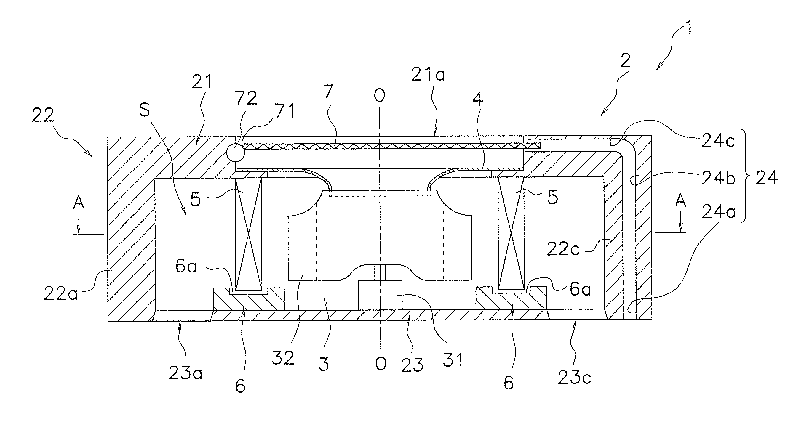
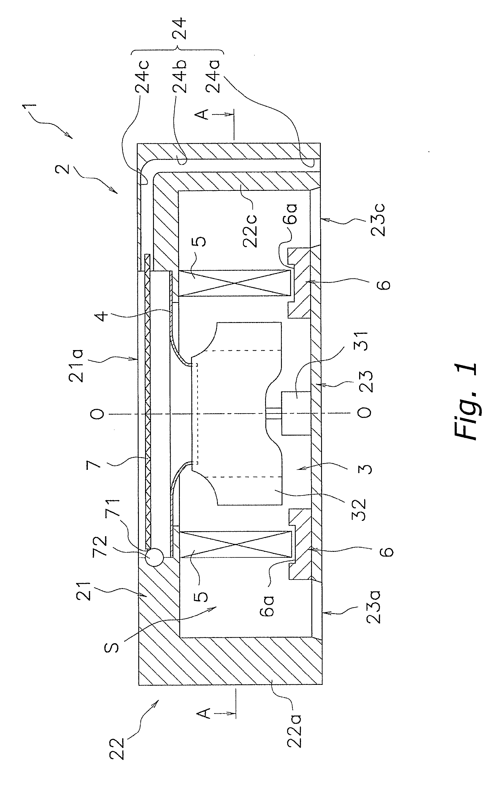
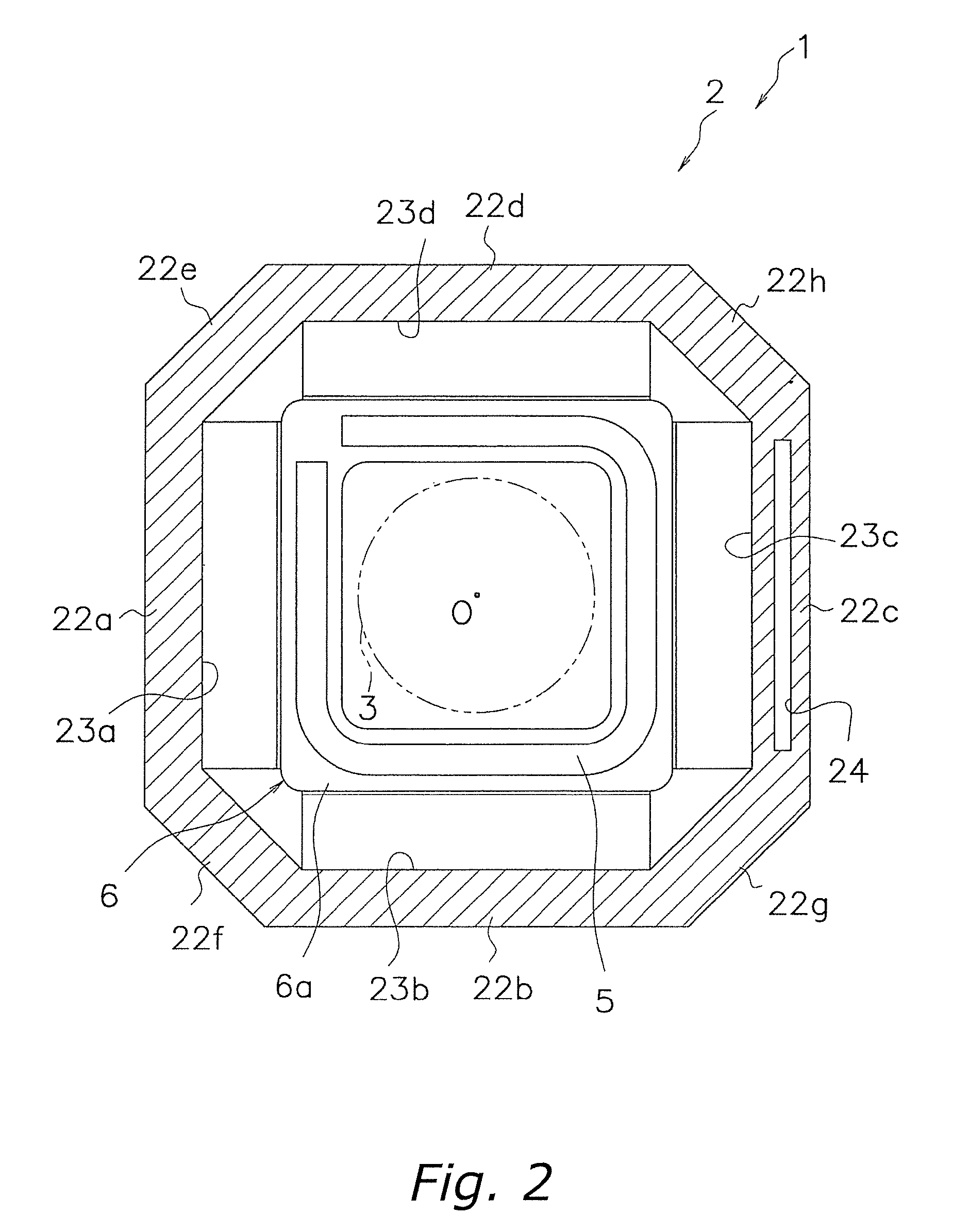
[0131]FIG. 1 shows a general side sectional view (with a ceiling being omitted) of a ceiling-mounted air conditioner 1 pertaining to a first embodiment of the present invention, and FIG. 2 shows a cross-sectional view along A-A of FIG. 1. The air conditioner 1 is capable of corresponding to both a ceiling-embedded configuration and a ceiling-suspended configuration, and is mainly disposed with a casing 2 that houses various types of configural devices inside. It will be noted that O in the drawings represents an axis-of-rotation line or a rotational center of a blow fan 3.

[0132]In the present embodiment, the casing 2 is a box-like member whose shape when seen in a plan view is substantially octagonal, and the casing 2 mainly includes a substantially octagonal top plate 21 whose long sides and short sides are formed so as to be alternately continuous, a side plate 22 that extends downward from the peripheral edge portion of th...

modification 4

(8) Modification 4

[0164]In the air conditioner 1 pertaining to the preceding embodiment and modifications 1 to 3, a heat exchanger is disposed on the downstream side of the blow fan 3 in the air flow path S, but instead of disposing a heat exchanger on the downstream side of the blow fan 3, a heat exchanger may be disposed on the upstream side, or a heat exchanger may be disposed on the downstream side of the blow fan 3 and a heat exchanger may be disposed on the upstream side. For example, taking as an example the case of the configuration in modification 3 (see FIG. 8 and FIG. 9), as shown in FIG. 13, a heat exchanger 105 can be disposed on the upstream side of the blow fan 3 between the filter 7 and the bellmouth 4 instead of the heat exchangers 5 that are disposed on the downstream side of the blow fan 3, or, as shown in FIG. 14, the heat exchanger 105 can be disposed on the upstream side of the blow fan 3 between the filter 7 and the bellmouth 4 in addition to the heat exchange...

second embodiment

(1) Basic Configuration of Ceiling-Mounted Air Conditioner

[0217]The preceding first embodiment and its modifications were of the ceiling-mounted air conditioner 1 of a configuration disposed with the casing 2 in whose top surface or side surface is formed a suction opening, the blow fan 3 that comprises a turbo fan or a diagonal flow fan disposed inside the casing 2, and the heat exchanger 5 that is disposed inside the casing 2, but as shown in FIG. 40, the invention may also be an air conditioner 401 disposed with a configuration where a blow fan 403 that comprises a sirocco fan and a heat exchanger 405 are housed inside a casing 402 in whose side surface is formed a suction opening 421a and in whose bottom surface is formed a blowout opening 423a. Below, the basic configuration of the air conditioner 401 of the present embodiment will be described.

[0218]The casing 402 is a substantially rectangular box-like member that houses the heat exchanger 405 and the blow fan 403 inside, wi...


PUM

PropertyMeasurementUnit
Weightaaaaaaaaaa
Forceaaaaaaaaaa
Flow rateaaaaaaaaaa

Abstract

An air conditioner is installable in a ceiling of an air-conditioned room and is disposed with a casing in whose top surface is formed a suction opening and in whose bottom surface are formed blowout openings, and in which is formed an air flow path that leads from the suction opening to the blowout openings, a blow fan that is disposed in the air flow path, and a heat exchanger that is disposed in the air flow path.

Description

TECHNICAL FIELD[0001]The present invention relates to an air conditioner and particularly to a ceiling-mounted air conditioner where a blowout opening is disposed in a bottom surface of a casing.BACKGROUND ART[0002]As a conventional ceiling-mounted air conditioner, there is an air conditioner disposed with a casing in whose bottom surface a suction opening and a blowout opening are formed and a blow fan and a heat exchanger that are disposed inside the casing.DISCLOSURE OF THE INVENTION[0003]However, there has been the problem that, when both the suction opening and the blowout opening are formed in the bottom surface, it is easy for a phenomenon (called “short circuiting of air flow” below) to occur where air that is blown out from the blowout opening ends up being sucked back inside the casing from the suction opening immediately after being blown out, and indoor comfort is impaired.[0004]It is an object of the present invention to make it more difficult for short circuiting of ai...

Claims


Application Information

Patent Timeline
IPC IPC(8): F25D23/00F25D17/06F25B39/02C07C209/90B01J2/12F24F1/0047C07C67/00C07C209/00C07C209/82C07C211/53F24F1/0063F24F1/0073F24F8/108F24F8/90
CPCF24F1/0007F24F3/1603F24F13/28F24F2013/0616F24F2001/0062F24F2003/1639F24F2001/0037F24F1/0047F24F1/00075F24F8/90F24F1/0073F24F1/0063F24F8/108F24F1/0011F24F1/0059F24F2221/22
Inventor YABU, TOMOHIROMATSUOKA, HIROMUNETAKENAKA, NORIHIROMORIZANE, TETSUYA
Owner DAIKIN IND LTD
Why Eureka
Try Eureka