Distribution valve and method

a technology of distribution valve and valve body, which is applied in the direction of valve operating means/release devices, water supply installation, transportation and packaging, etc., can solve the problems of gear reduction mechanism “locking up”, gear reduction mechanism breaking, and gears in the planetary gear assembly. , to achieve the effect of reducing maintenance and repair costs and downtim

Inactive Publication Date: 2009-08-27
TIPOTSCH DONALD
View PDF3 Cites 20 Cited by
  • Summary
  • Abstract
  • Description
  • Claims
  • Application Information

AI Technical Summary

Benefits of technology

[0006]It is an object of the invention to provide an improved distribution valve with a longer life gear reduction assembly, cam device and housing which substantially reduces maintenance and repair costs and downtime.

Problems solved by technology

Unfortunately, a fairly large force is required to be applied by the gear reduction mechanism to rotate the cam device that pushes the valve balls away from their valve seats in order to open the valves.
The increased amount of required torque greatly increases the amount of stress on the gears of the planetary gear assembly resulting in “locking up” of the gear reduction mechanism and the breaking of the gears in the planetary gear assembly.
This results in increased repair and maintenance and downtime for the pool system.
In addition the spherical acrylic valve balls often get debris embedded in them which then abrades the cam device when it rotates as well as abrading the distribution valve housing.

Method used


Image

  • Distribution valve and method
  • Distribution valve and method
  • Distribution valve and method

Examples


Embodiment Construction

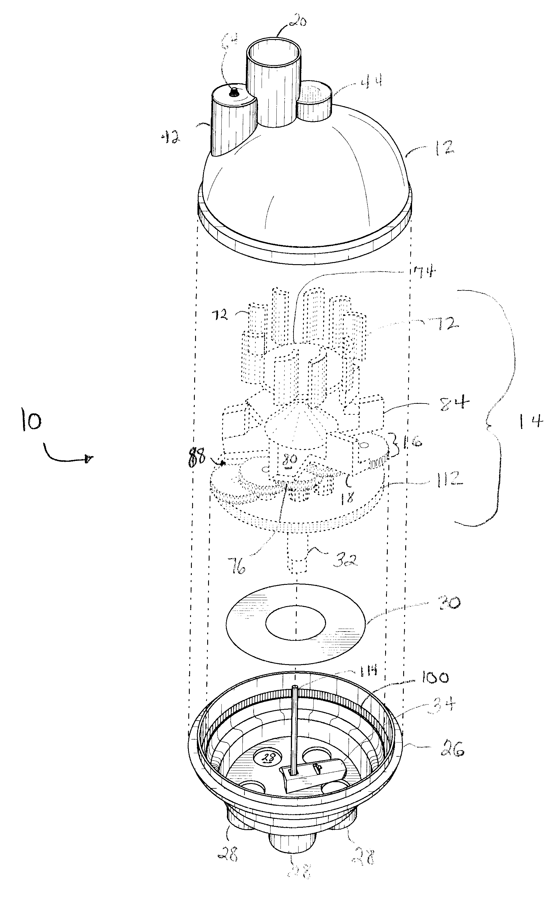
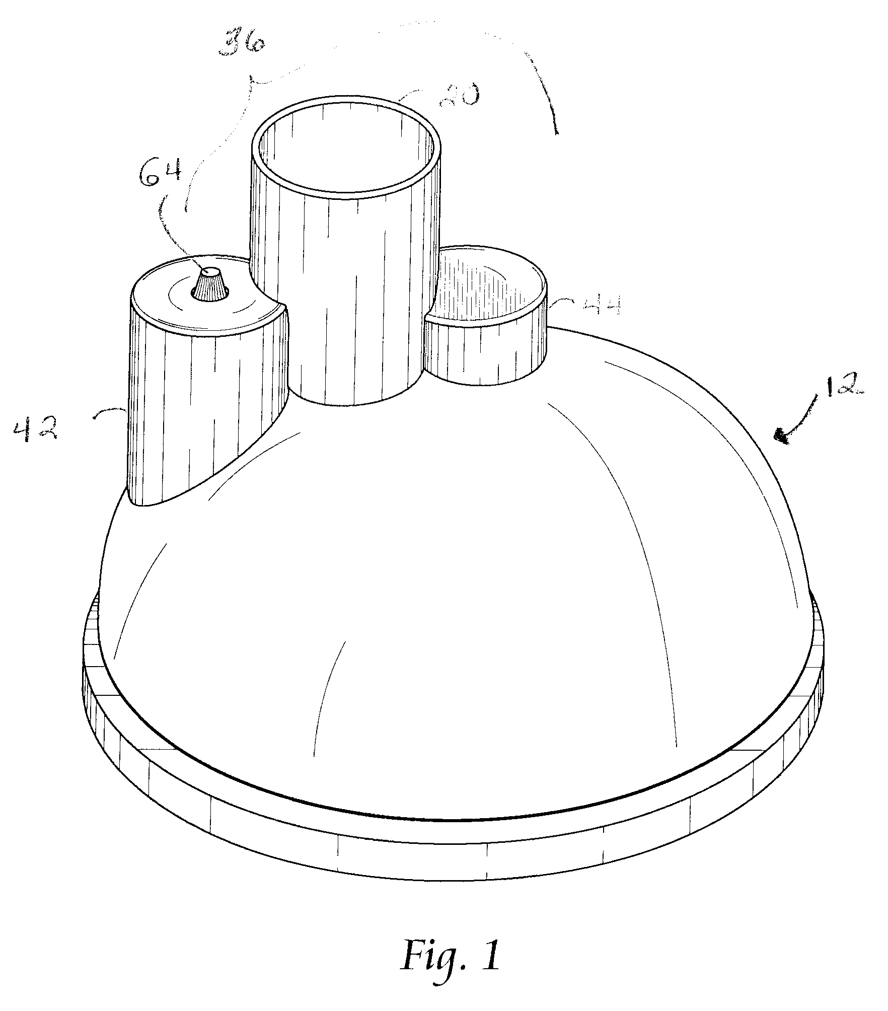
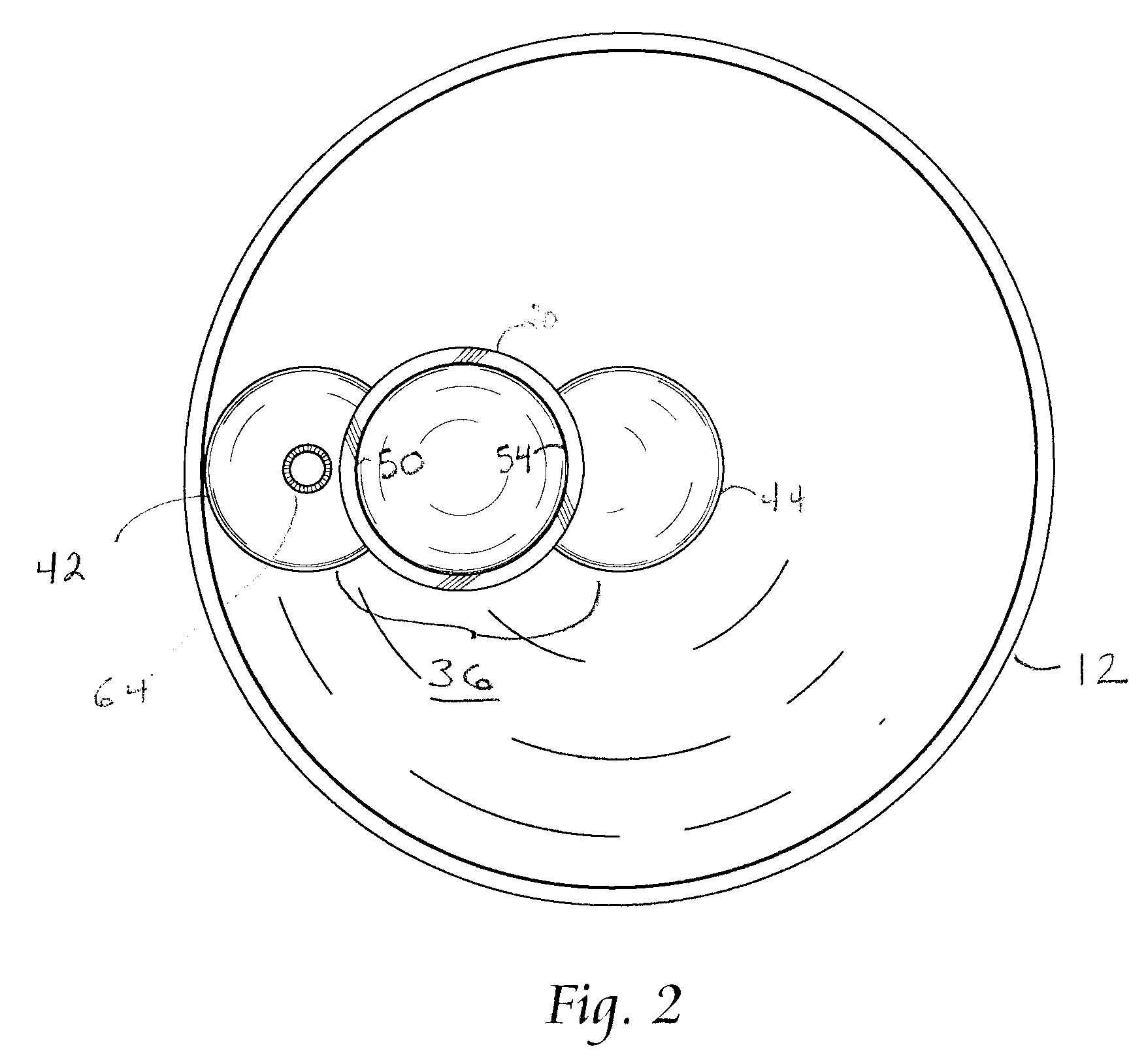
[0029]As shown in the drawings for purposes of illustration, the present invention is concerned with an improved distribution valve, generally designated in the accompanying drawings by the reference number 10. The improved distribution valve 10 comprises, generally, an upper housing section 12, a gear reduction assembly 14 inside the upper housing section 12, the gear reduction assembly 14 including a gear reduction mechanism 16 and an impeller 18 located in fluid communication with a fluid inlet port 20 and connected to a rotary input shaft 22 to drive the gear reduction mechanism 16, a lower housing valve assembly 24 adapted for sealing engagement with the upper housing section 12 and comprised of a lower housing section 26 having a plurality of fluid outlet ports 28, a substantially pliable annular disc 30 that overlies the plurality of fluid outlet ports 28 and disposed on a rotary output shaft 32 of the gear reduction mechanism 16, and a cam device 34 engaging the rotary outpu...


PUM


Abstract

An improved distribution valve is provided that distributes water from a swimming pool pump to cleaning heads located along the inner surface of a swimming pool. The distribution valve includes a housing having a fluid inlet and a plurality of fluid outlet ports. The housing includes a lower section and a removable upper section. A gear reduction assembly located in the housing includes a gear reduction mechanism and impeller located near the inlet port and connected to a rotary input shaft of the gear reduction mechanism. A cam device engages a rotary output shaft of the gear reduction mechanism so as to rotate the cam device in response to rotation of the impeller. The cam device rotates under a pliable annular disc on the rotary output shaft and lifts and lowers portions of the annular disc to sequentially open and close fluid paths through the fluid outlet ports.
The improved distribution valve may include a bypass chamber with a rotatable drum therein and a diffusion chamber in fluid communication with the fluid inlet. The drum wall includes a cutout. The drum is rotatable to fully or partially align the cutout with a bypass chamber inlet to permit water flow through the bypass chamber to help rotate the impeller. The impeller speed may be controlled by adjusting the water flow through the bypass chamber. The more water flow, the faster the impeller rotates. The drum is also rotatable to block the bypass chamber inlet to prevent water flow through the bypass chamber, in which case water from the diffusion chamber rotates the impeller. Impeller rotation will be at a slower speed due to the decreased water flow.

Description

FIELD OF THE INVENTION [0001]This invention relates generally to distribution valves for distributing water from a swimming pool pump to cleaning heads located along the inner surface of a swimming pool. More specifically, this invention relates to an improved distribution valve that optimizes water flow to outlet ports without using complicated valve assemblies while minimizing stress and tension on the gear assembly while substantially eliminating leaking.BACKGROUND OF THE INVENTION [0002]Distribution valves receive water from the high-pressure side of a swimming pool pump through an inlet port and distribute the water under high pressure through sequential outlet ports to various groups of cleaning heads located along the inner surface of a swimming pool.[0003]A number of multi-port distribution valves are known. These include the distribution valves described in U.S. Pat. Nos. 4,523,606 and 4,570,663 commonly assigned to Shasta Industries, Inc. Each of the distribution valves di...

Claims


Application Information

Patent Timeline
Patent Type & Authority Applications(United States)
IPC IPC(8): F16K31/52F16K11/06
CPCF16K11/074F16K31/52483F16K31/16Y10T137/86501Y10T137/86911Y10T137/0318
Inventor TIPOTSCH, DONALD
Owner TIPOTSCH DONALD
Why Eureka
Try Eureka