System and Method for Continuous Rapid Cooling of Molten Materials to Produce Uniformly-Shaped Solid Forms

a technology of molten materials and solid forms, which is applied in the direction of heat transfer modification, indirect heat exchangers, lighting and heating apparatus, etc., can solve the problems of large floor space and capital and space requirements of systems, and achieve the effect of rapid change of process and system, increasing productivity and/or forming rates, and providing flexibility

Inactive Publication Date: 2009-08-27
NEAL DENNIS EDWIN
View PDF19 Cites 0 Cited by
  • Summary
  • Abstract
  • Description
  • Claims
  • Application Information

AI Technical Summary

Benefits of technology

[0011]Accordingly, one feature and advantage of the system and method of the present invention is the ability to provide uniformity in product form not presently attainable by prior art systems and / or methods.
[0012]Another feature and advantage of the system and method of the present invention is the ability to provide flexibility to quickly change the process and system to produce alternate shapes.
[0013]Another and further feature and advantage of the system and method of the present invention is to provide a means to label and / or mark each product form in a manner not presently attainable by prior art systems and / or methods.
[0014]Another and still further feature and advantage of the system and method of the present invention is to increase productivity and / or forming rates over that presently attainable by prior art systems and / or methods by using appropriate ancillary equipment and coolant media.
[0015]Another feature and yet still further advantage of the system and method of the present invention is to provide such functionality and features with lesser capital outlay than prior art methods, and which system occupies a fraction of the floor space required through use of prior art systems and / or methods.

Problems solved by technology

Such systems require a large amount of floor space.
Such systems are, accordingly, both capital and space intensive, and can, therefore, be undesirable.

Method used


Image

  • System and Method for Continuous Rapid Cooling of Molten Materials to Produce Uniformly-Shaped Solid Forms
  • System and Method for Continuous Rapid Cooling of Molten Materials to Produce Uniformly-Shaped Solid Forms
  • System and Method for Continuous Rapid Cooling of Molten Materials to Produce Uniformly-Shaped Solid Forms

Examples


Embodiment Construction

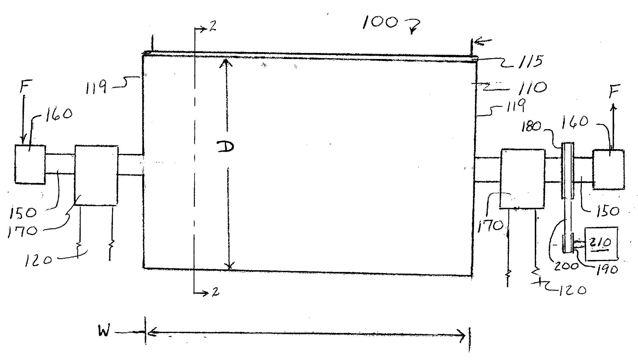
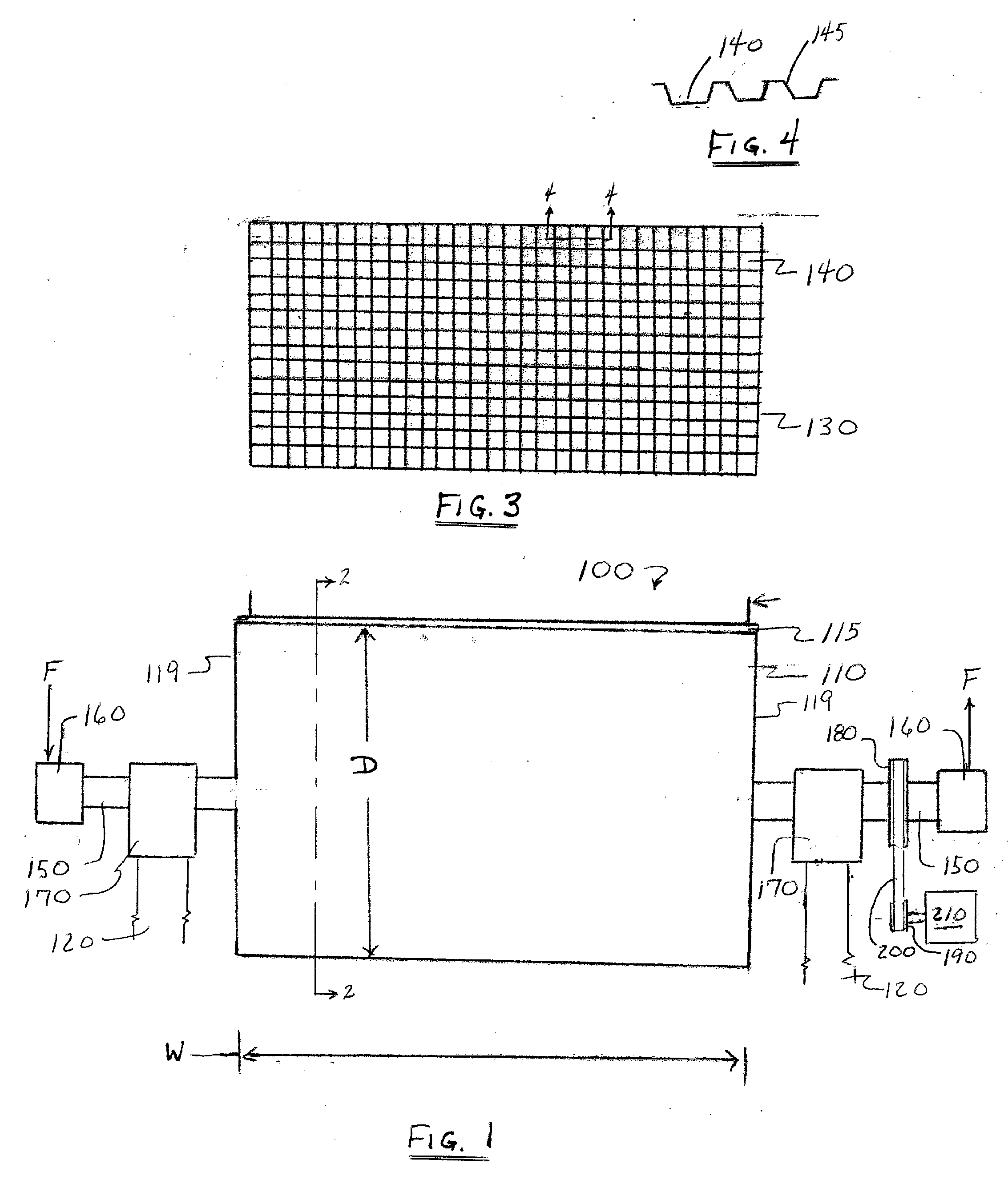
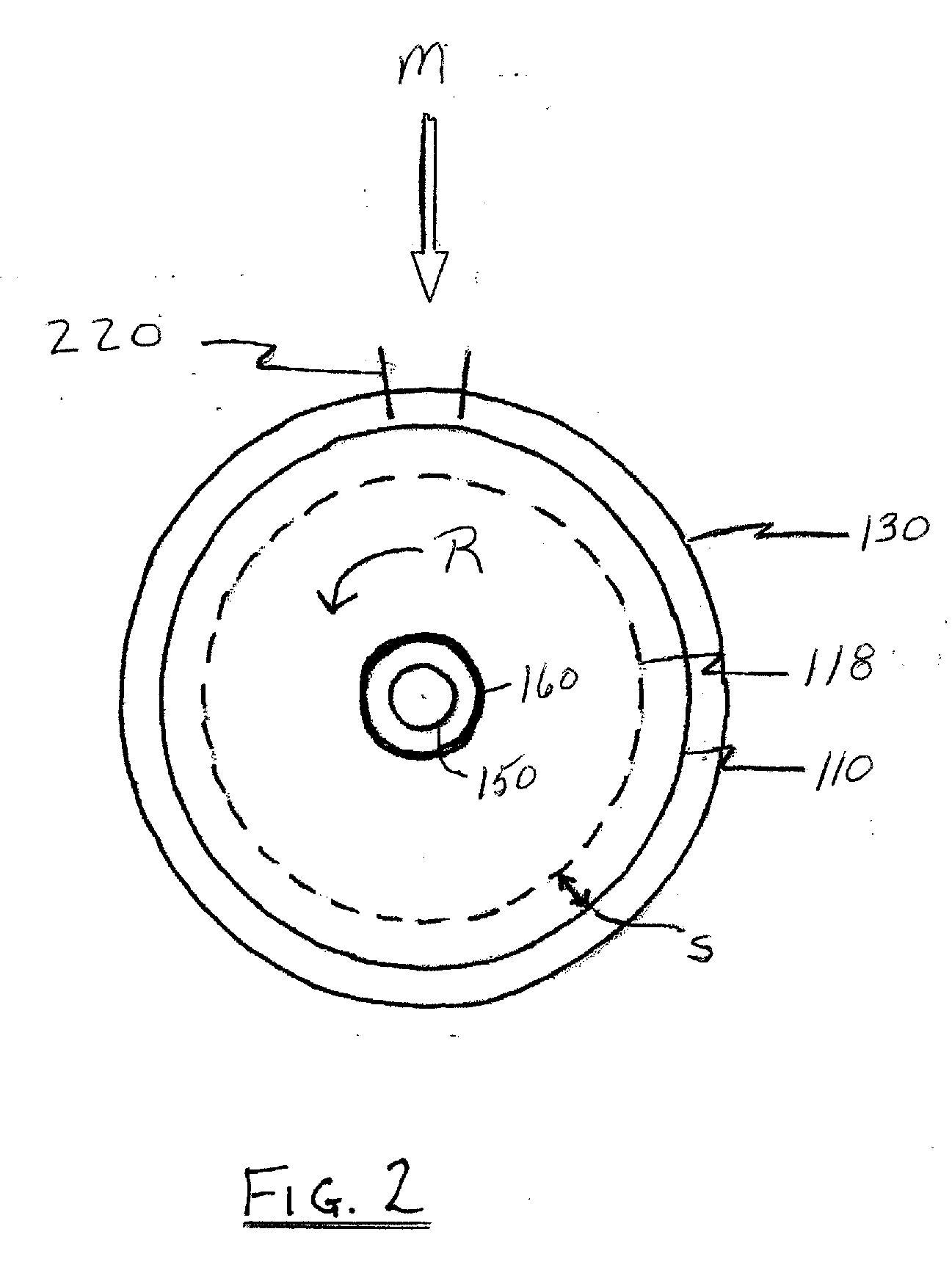
[0023]In describing preferred embodiments of the system and method of the present disclosure illustrated in the drawing Figures, specific terminology is employed for the sake of clarity. The claimed invention, however, is not intended to be limited to the specific terminology so selected, and it is to be understood that each specific element includes all technical equivalents that operate in a similar manner to accomplish a similar purpose.

[0024]It will be further understood that the terms, “chemical,” and “material,” and their respective plural forms, as used herein, are intended to describe any of a variety of those organic and / or inorganic chemicals, compounds, materials, composites, emulsions, solutions, and the like, that go through a phase change from a fluid form, and typically a molten fluid form, to become a solid upon cooling. By way of non-limiting example, such materials might comprise glues, adhesives, plastics, and the like.

[0025]The invention disclosure set forth here...


PUM

PropertyMeasurementUnit
heat transferaaaaaaaaaa
heataaaaaaaaaa
distanceaaaaaaaaaa

Abstract

A system and method is disclosed for rapid cooling of hot molten liquid chemicals, and other materials, that go through a phase change to become a solid upon cooling, formed continuously on a single, rotating cylinder having detachable molds, to produce a high volume of uniformly shaped, solid forms.

Description

RELATED APPLICATIONS[0001]Priority is claimed to U.S. provisional patent application Ser. No. 61 / 066,855 filed on Feb. 22, 2008.TECHNICAL FIELD[0002]The present disclosure relates generally to rapid cooling of chemicals and molten materials, and, more particularly, to a system and method for rapid cooling of hot molten liquid chemicals, and other materials, that go through a phase change to become a solid upon cooling, formed continuously on a single, rotating cylinder having detachable molds, to produce a high volume of uniformly shaped, solid forms.BACKGROUND OF THE INVENTION[0003]Conventional systems for cooling molten chemicals and other materials that go through a phase change from a liquid or molten form to a solid form, often comprise a system whereby molten materials are dropped or forced onto, and are thereafter usually spread upon, one or more linear belts for cooling. Such systems require a large amount of floor space. Additionally, such systems typically require the use ...

Claims


Application Information

Patent Timeline
Patent Type & Authority Applications(United States)
IPC IPC(8): F28F13/12
CPCF28D11/02
Inventor NEAL, DENNIS EDWIN
Owner NEAL DENNIS EDWIN
Why Eureka
Try Eureka