
Inherently failsafe electric power steering system

a power steering system, inherently failsafe technology, applied in the direction of steering initiation, instruments, vessel construction, etc., can solve the problems of system reverting to manual steering, inherently failsafe operation, and inability to use ehps systems in future vehicles, etc., to achieve the effect of improving the steering feel

Inactive Publication Date: 2009-08-27
TECHCO
View PDF7 Cites 0 Cited by
  • Summary
  • Abstract
  • Description
  • Claims
  • Application Information

AI Technical Summary

Benefits of technology

The system provides inherently failsafe operation, eliminating motor inertia feedback and improving steering feel, especially at high speeds and during on-center conditions, thus offering superior stability and accuracy compared to traditional EPS systems.

Problems solved by technology

Because such motors directly deliver steering force, all EPS systems must have an absolute failsafe shutdown mode that unfailingly causes the system to revert to manual steering in the event of any sub-system failure.
Since a driver directly controls steering motion in a vehicle equipped with an EHPS system, they are inherently failsafe in operation.
EHPS systems are not considered acceptable for utilization in future vehicles however, because they waste a significant percentage of the pressurized fluid in all but “accident avoidance” maneuvers in order to effect differential output pressure control.
Thus they are in general not capable of being utilized for vehicles with larger steering loads, such as for instance, typical medium sized automobiles.
In all presently known EPS systems however (e.g., even including the hydro-mechanically coupled EPS system described in the incorporated '254 patent), all shutdown modes are software controlled and electronically implemented whereby there exists a finite possibility that all such shutdown modes could simultaneously fail and that a resulting runaway steering event could occur.
This possibility is exacerbated by the fact that apparatus supporting these safety shutdown modes must survive indefinitely through changes of vehicle ownership, indifferent maintenance scenarios, and even tinkering by unqualified individuals.
Further and similarly to all other known EPS systems, the hydro-mechanically coupled EPS system described in the incorporated '254 patent has the undesirable characteristic of reflecting motor inertia back to the vehicle's steering wheel whenever negligible power assist is required such as during on-center operation and / or at very high vehicular speeds.
This is especially bothersome because the motor inertia is compliantly coupled to the steering wheel (i.e., via a torsion bar).

Method used


Image

  • Inherently failsafe electric power steering system
  • Inherently failsafe electric power steering system
  • Inherently failsafe electric power steering system

Examples


Embodiment Construction

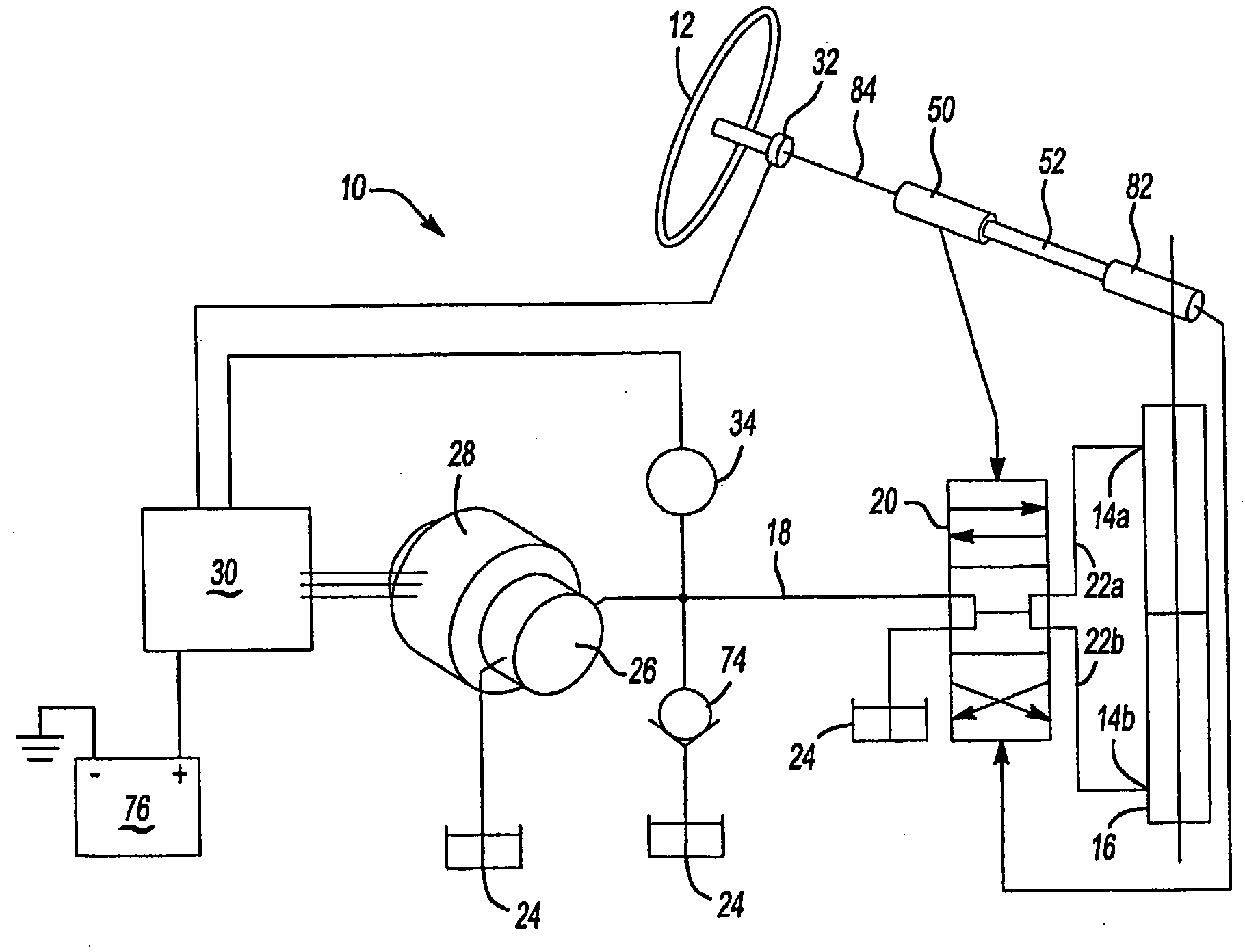
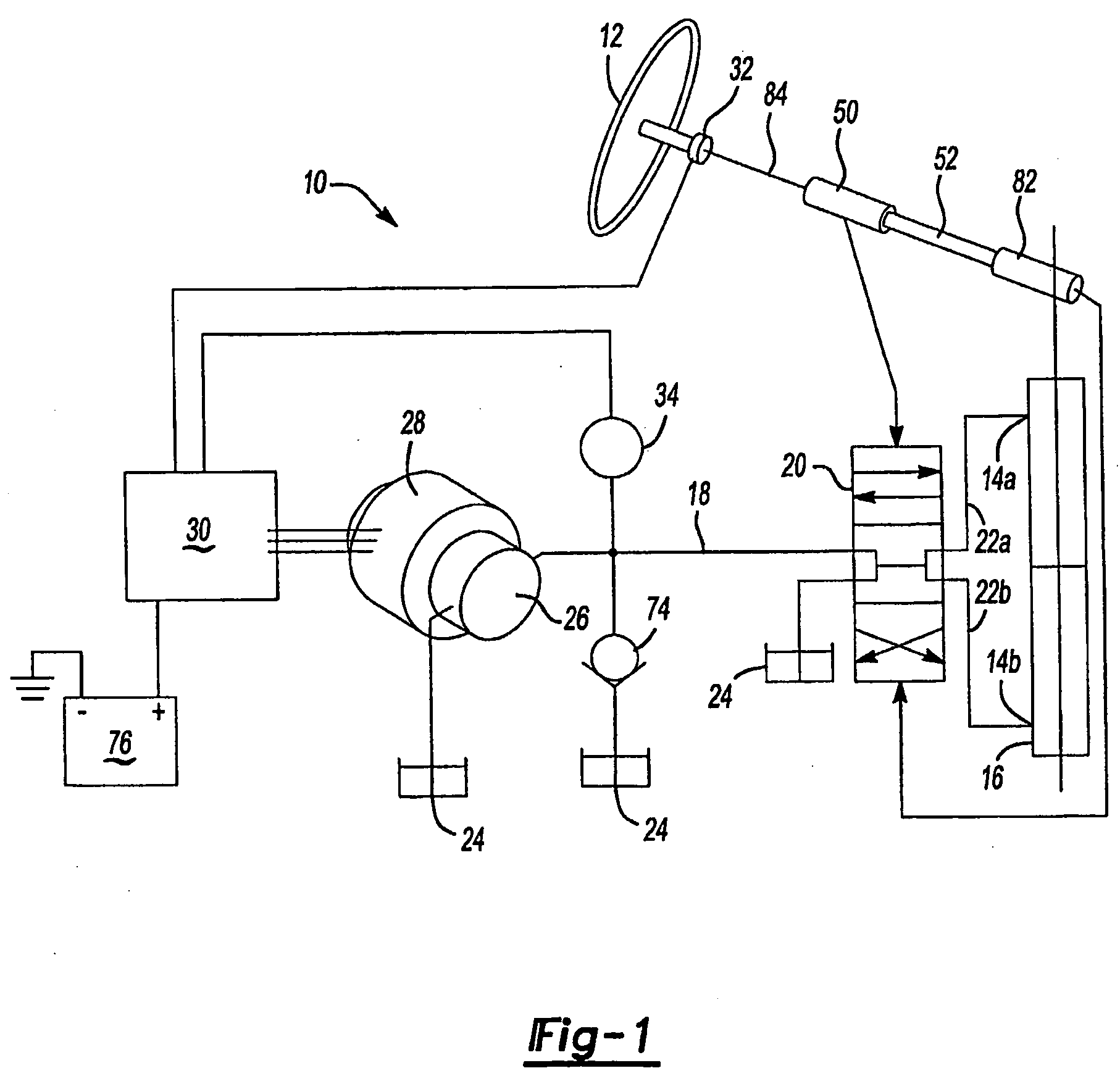
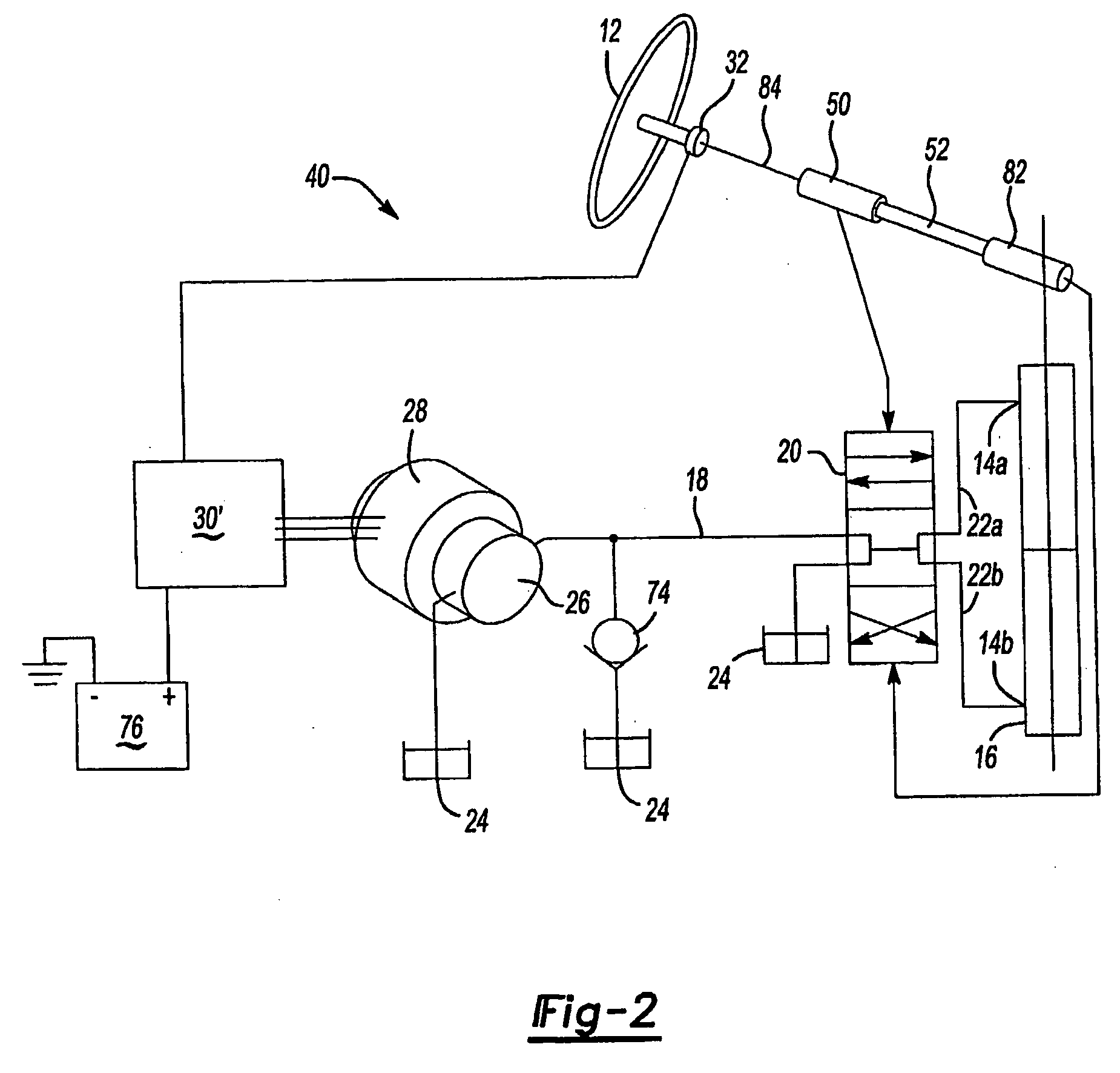
[0022]With reference first to FIG. 1, there shown is an inherently failsafe hydro-mechanically coupled EPS system 10 according to the present invention that is generically related to and controlled in a similar manner as the EPS system with hydraulic transmission (10) described in detail in the incorporated '254 patent. In the inherently failsafe hydro-mechanically coupled EPS system 10 however, pressurized fluid is provided to a directional control valve 20 in response to torque applied by a driver to a steering wheel 12. The directional control valve 20 may be an under-lapped four-way valve. When torque is applied in sufficient amount to effect translation through and beyond the underlap region of the directional control valve 20, the pressurized fluid is conveyed to or from one of left and right ports 14a and 14b of a double-acting power cylinder 16 via a fluid line 18, the directional control valve 20, and one of respective left and right turn lines 22a and 22b. Low pressure (he...


PUM


Abstract

An electronically controlled hydro-mechanically coupled power steering system includes a double-acting power cylinder having a directional control under-lapped four-way open center valve and a motor driven pump. A controller selectively provides pressurized fluid to the double-acting power cylinder to function in the manner of an inherently failsafe EPS system.

Description

[0001]This application claims priority to U.S. Provisional Application Ser. No. 60 / 621,797 filed Oct. 25, 2004.BACKGROUND OF THE INVENTION[0002]The present invention relates generally to power steering systems for vehicles, and more particularly to hydro-mechanically coupled electrically powered steering systems.[0003]Currently it is anticipated that an overwhelming majority of vehicular power steering systems will be electrically powered in the future. Most common will be electric power steering systems (hereinafter “EPS systems”) wherein motors directly deliver steering force as a function of current applied to them by a controller. Because such motors directly deliver steering force, all EPS systems must have an absolute failsafe shutdown mode that unfailingly causes the system to revert to manual steering in the event of any sub-system failure. Such shutdown modes must at a minimum deactivate the system motor.[0004]On the other hand, electro-hydraulic power steering systems (her...

Claims


Application Information

Patent Timeline
Patent Type & Authority Applications(United States)
IPC IPC(8): B62D5/06B62D6/00
CPCB62D5/065
Inventor PHILLIPS, EDWARD H.
Owner TECHCO
Learn More