Articulated Mounting Systems And Bearings For Joints Thereof

a technology of mounting system and mounting bearing, which is applied in the direction of mechanical control devices, process and machine control, instruments, etc., can solve the problems of affecting the installation efficacy and ease of manipulation, the position of the display device to move or slip, and the difficulty of prior art installation of articulated mounting arms, etc., to achieve the effect of convenient adjustment and fixing

Inactive Publication Date: 2009-08-27
MOUNT LOGIC
View PDF8 Cites 59 Cited by
  • Summary
  • Abstract
  • Description
  • Claims
  • Application Information

AI Technical Summary

Benefits of technology

[0008]The present disclosure describes several features for use in articulated mounting arm systems. A first of these features is an indexed bearing that is resistant to gravitational drag on the joints of an articulated mounting arm system. A second feature is a telescoping ceiling mount system that allows the height of the vertical ceiling mount tube to be easily adjusted and fixed. A fourth feature is a vertical leveling system for ensuring

Problems solved by technology

Prior designs of articulated mounting arms for supporting various display devices, for example, televisions, computer monitors, and flat panel displays suffer from several problems that negatively impact the installation efficacy and ease of manipulation when in use.
One such problem is gravity drift wherein the force of gravity on the display device and the mounting structure itself causes the position of the display device to move or slip because the joints are unable to withstand the force of gravity.
A second problem concerns the difficulty of installation of prior art articulated mounting arms.
For example, ma

Method used


Image

  • Articulated Mounting Systems And Bearings For Joints Thereof
  • Articulated Mounting Systems And Bearings For Joints Thereof
  • Articulated Mounting Systems And Bearings For Joints Thereof

Examples


Embodiment Construction

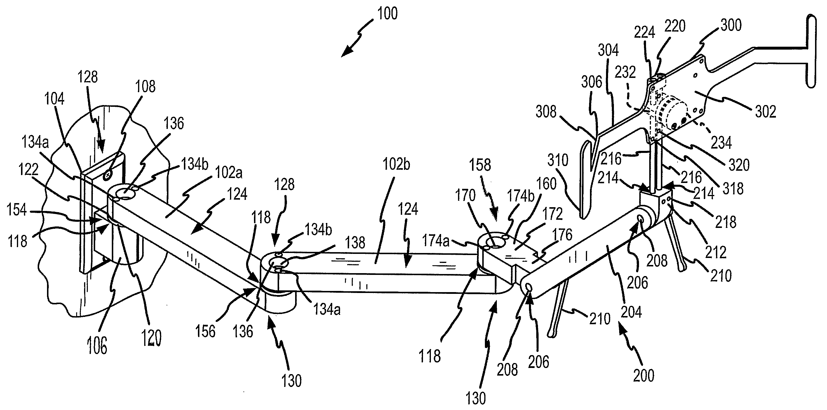
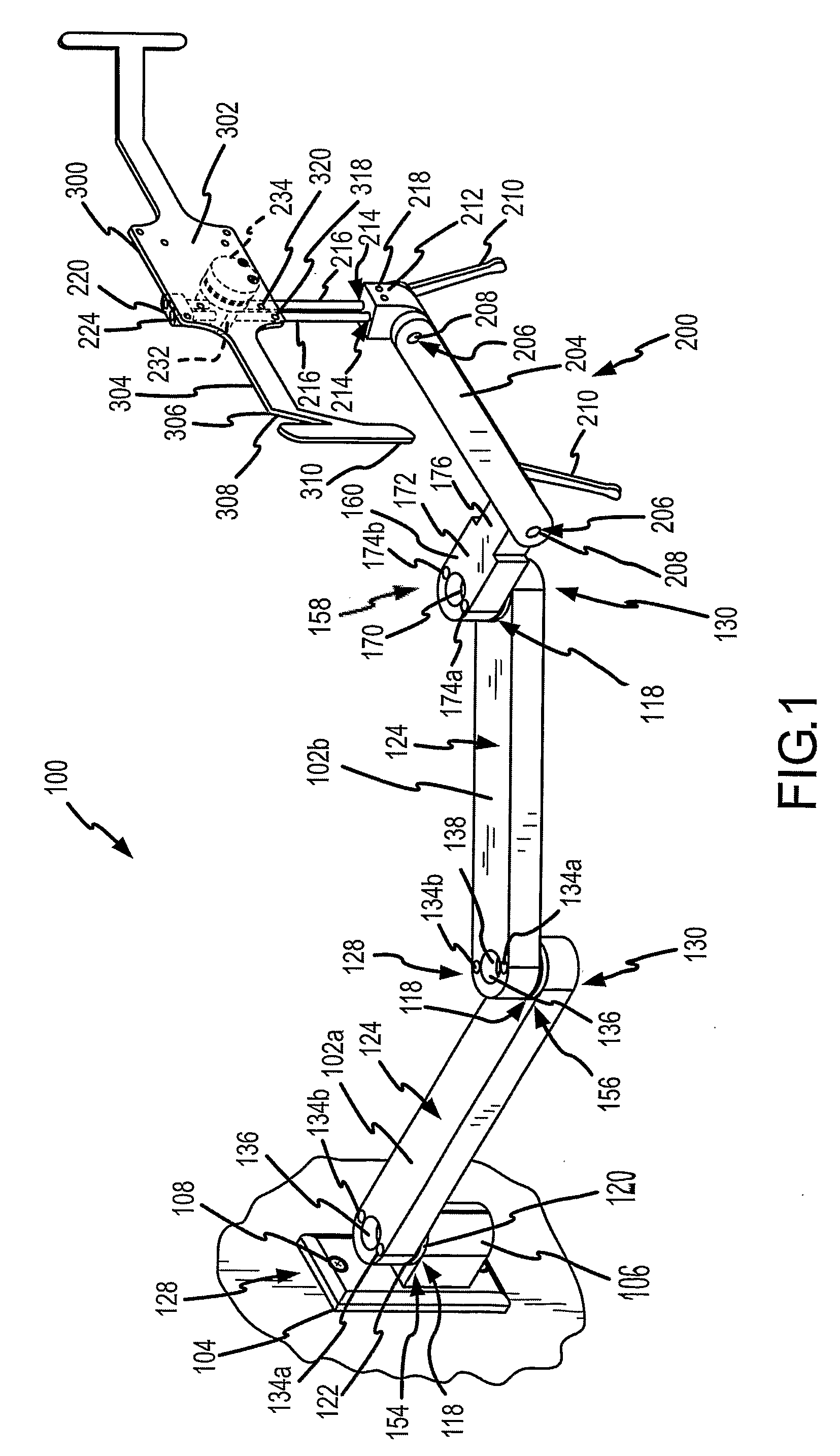
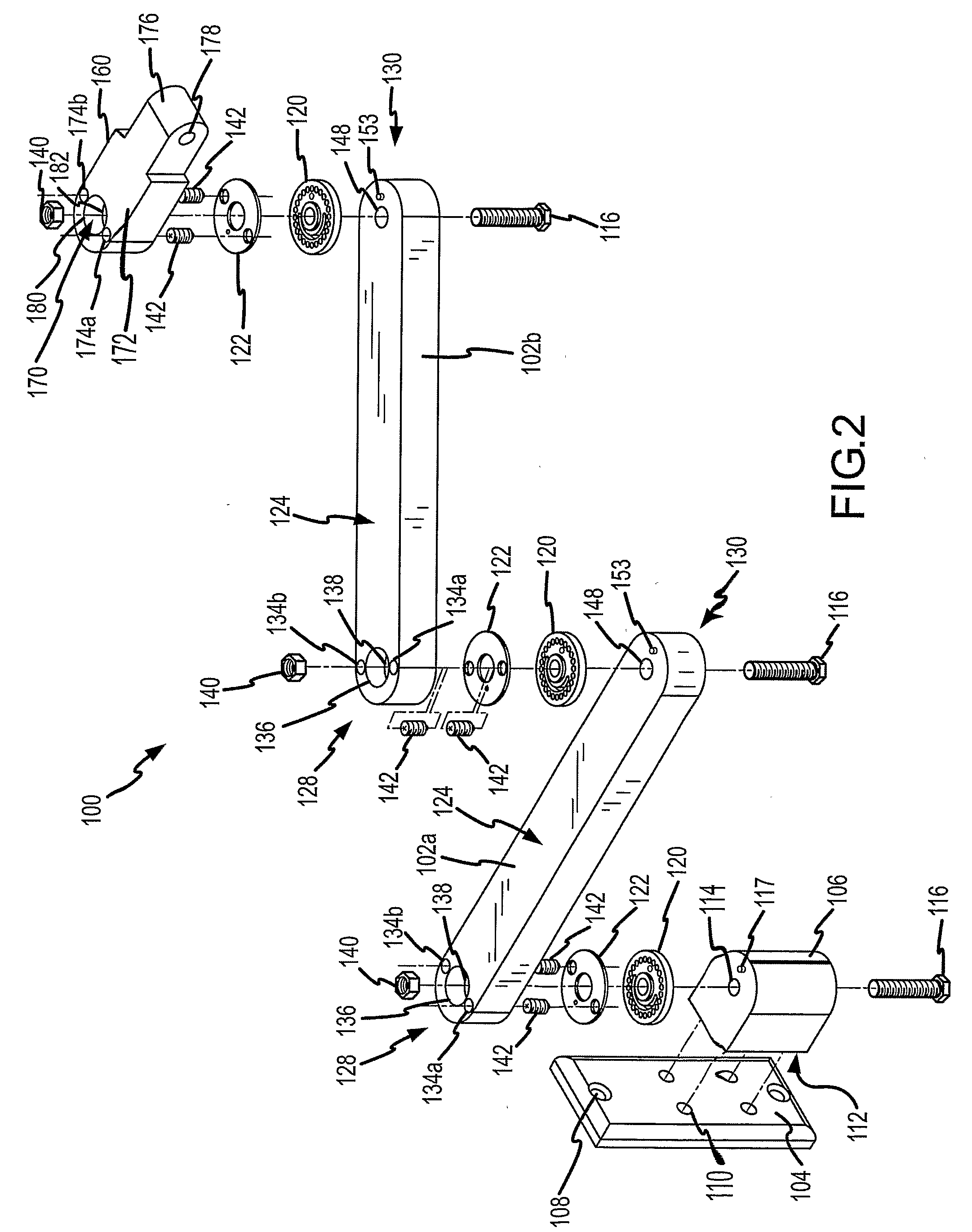
[0038]FIGS. 1 and 2 depict an articulated wall mount system 100 for supporting a device, for example, a television, computer monitor, flat panel display, or other video display device, audio or video control system, medical equipment, a task light, or any other piece of equipment. The articulated wall mount system 100 may support additional related items, for example, a computer keyboard tray, computer mouse tray, or other supports for related computer peripheral equipment.

[0039]The articulated wall mount system 100 may comprise one or more members extending from and mounted to a wall via a wall bracket 104. The wall bracket 104 may have a number of mounting apertures 108 through its face at both the top and bottom of the wall bracket 104. The mounting apertures 108 are designed to accept fastening devices, for example, lag bolts, which may be used to secure the wall bracket 104 to a vertical surface, for example, a wall or preferably a structural member of the wall, for example, a ...


PUM


Abstract

An articulated mounting system (100) includes indexed bearings (118) at joints (154, 156, 158) between two members (102a, 102b, 106, 160) that provide stepped rotational movement between the two members (102a, 102b, 106, 160). The indexed bearings (118) are resistant to gravitational slippage. The indexed bearings (118) maintain the position of the joint (154, 156, 158) with tightening the joint (154, 156, 158) and allow for rotational movement of members about the joint (154, 156, 158) without loosening. An adjustable, vertically-oriented, ceiling mount system has leveling mechanism for ensuring that the telescoping tubes are vertically plum. A display mount (300) has handles (310) for allowing adjustment of the position of the mounting system members (102a, 102b, 106, 160) and the angle of display while maintaining a sterile operating field.

Description

CROSS REFERECE TO RELATED APPLICATIONS[0001]This application claims priority pursuant to 35 U.S.C. §119(e) to U.S. provisional application No. 60 / 645,799 filed 20 Jan. 2005, which is hereby incorporated by reference herein in its entirety.BACKGROUND OF THE INVENTION[0002]1. Field of the Invention[0003]This invention relates to articulated arms for mounting televisions, computer monitors, and other displays to walls, ceilings, and other surfaces.[0004]2. Description of the Related Art[0005]Prior designs of articulated mounting arms for supporting various display devices, for example, televisions, computer monitors, and flat panel displays suffer from several problems that negatively impact the installation efficacy and ease of manipulation when in use. One such problem is gravity drift wherein the force of gravity on the display device and the mounting structure itself causes the position of the display device to move or slip because the joints are unable to withstand the force of gr...

Claims


Application Information

Patent Timeline
IPC IPC(8): A47F5/10G05G5/06A47F5/06
CPCF16M11/04F16M11/10F16M11/2014F16M11/2064Y10T74/20636F16M13/02F16M2200/024F16M2200/068F16M11/28
Inventor BOURGEOIS, BARRY K.BRADBURY, JAMES R.SHERWOOD, STEVEN A.
Owner MOUNT LOGIC
Why Eureka
Try Eureka