Voltage transformer with sequentially switchable voltage selection circuit

a voltage selection circuit and voltage transformer technology, applied in the direction of ignition automatic control, coupling device connection, instruments, etc., can solve the problems of incorrect output voltage, unstable output voltage or even incorrect voltage, damage of electrical products, etc., to eliminate the risk of damage to products, eliminate the risk of false touch generation, and reduce the hassle of carrying and losing parts

Inactive Publication Date: 2009-08-27
KERIO TECHNOLOGIES INC
View PDF10 Cites 7 Cited by
  • Summary
  • Abstract
  • Description
  • Claims
  • Application Information

AI Technical Summary

Benefits of technology

[0009]Accordingly, an object of the present invention is to provide an extremely safe voltage transformer with a sequentially switchable voltage selection circuit that cannot supply power when it is switched to change voltages.
[0010]Another object of the present invention is to provide a voltage transformer with a sequentially switchable voltage selection circuit that can be switched to change output voltages only through feedback and can prevent the switching of the voltage transformer from false touch during power supply.
[0015]The switch connects the different circuit elements to the voltage transformation unit one by one through the feedback drive of the connection device, thereby changing the output voltage. This operation must be done by the user so there is no worry about false touch generation; and the connection device itself can be a connector for connecting the output port to the an electrical product such that when it is switched to output the voltages, it completely fails to supply power at the same time, thus eliminating the risk of damaging the product; there is no design of external parts so the hassle of carrying and losing the parts can be reduced. Particularly, the voltage display can be disposed at the power supply end to give the user clear information; and when it is switched to output the voltages, the output voltage values can be further feedback detected and self-calibrated. It can be said to kill several birds with one stone.

Problems solved by technology

However, such selective switches are easily led to abrasion owing to frequent switching, and it makes the switching and positioning of the voltage selector 15 gradually deviated or imperfectly contacted and thus outputs unstable voltages or even incorrect voltages.
When serious circumstances occur, it will result in damage of electrical products.
In particular, since most output voltage values are simply indicated by stickers, they might be displaced from or fall off their original positions due to long-term use as well, thus misguiding the user to give incorrect outputs.
Once false touch causes the voltage transformer to be switched, it is possible to result in the risk of hazard and damaging an electrical product.
By means of such structural design, an unexpected change in the voltage can be avoided during operation, but many pins 24 may cause the problem of easily losing and uneasily carrying them.
Similarly, many keys also cause the problem of carrying them.
If the keys were missed, it would become inconvenient in use.
The different buttons can be pressed in order to select and regulate the output voltages, but in one aspect the possibility of false touch generation is high.
The output voltage may be changed when false touch is created especially during power supply, thereby causing a decrease in the life span of the electrical product, even the safety problem and poor reliability.
Besides, the use of more expensive mechanical buttons would increase the cost of the voltage transformer.

Method used


Image

  • Voltage transformer with sequentially switchable voltage selection circuit
  • Voltage transformer with sequentially switchable voltage selection circuit
  • Voltage transformer with sequentially switchable voltage selection circuit

Examples


first embodiment

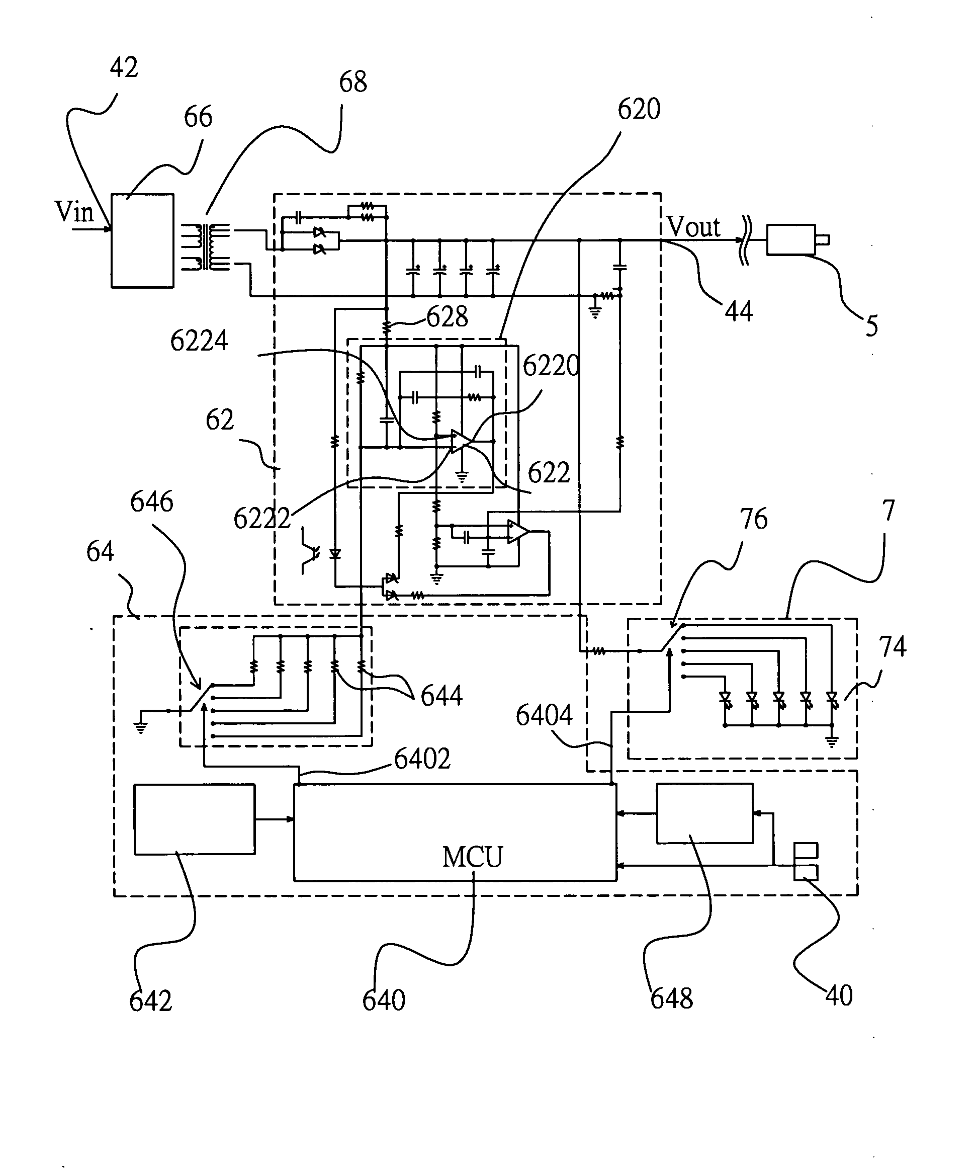
[0028]FIGS. 4 and 5 are a schematic view showing the appearance of and a schematic view showing the circuit of a first embodiment according to the present invention. In this embodiment, a general indoor power is taken as an example so that its input voltage is 110 volt AC, definitely, it will be readily apparent to those skilled in the art that the input voltage may also be 220 volt AC, or such as automotive 12 volt DC.

[0029]In this embodiment, the above input voltage Vin as electrical energy passes through a plug which serves as an input port 42, and is inputted into the circuits within the body 4, and an output voltage Vout, which is obtained from a voltage change generated by a sequentially switchable voltage selection circuit, passes through an output port 44 for outputting the electrical energy and an output conducting wire, which is electrically connected to a connection device 5, and then is supplied to an electrical product which utilizes the output electrical energy through...

third embodiment

[0039]Of course, as will be readily apparent to those skilled in the art, it is not restricted that the foresaid multiple circuit elements are alternately connected between the inverting input end of the amplifier and the ground. Also, as shown in FIG. 8 for the present invention, in the voltage regulator circuit 620″, the reference voltage Vref is similarly inputted into the non-inverting input end 6224″ of the amplifier 622″, which is fixedly connected to the resistor 628″ between the ground and the inverting input end 6222″. The microprocessor 640″ controls the switches 646″ to enable the different circuit elements 644″ to alternately connect between the output port and the inverting input end 6222″, and the effect of changing the resistance ratio of the resistors at the two sides can be similarly achieved, thereby changing the output voltage value.

fourth embodiment

[0040]Moreover, as shown in FIG. 9 for the present invention, in the voltage regulator circuit, the resistance ratio of the resistors at the two sides of the inverting input end 6222′″ of the amplifier 622′″ can be fixed, and the multiple switches 646′″ are conduction-connected to the microprocessor 640′″, and the different resistors 644′″ are changed and connected to the non-inverting input end 6224′″. Thus, the resistance ratio of the resistors 644′″ to 628′″ at the two sides of the non-inverting input end 6224′″ is changed to determine the reference voltage value at the non-inverting input end 6224′″, and the voltage at the inverting input end 6222′″ would follow the reference voltage, thus changing the final output voltage value.

[0041]Still further, as shown in FIG. 10 for a fourth embodiment of the present invention, in consideration of a microprocessor 640″″ having an output end 6400″″, when the above connection device is plugged in the socket portion, the output end 6400″″ wo...


PUM

PropertyMeasurementUnit
input voltagesaaaaaaaaaa
input voltageaaaaaaaaaa

Abstract

A voltage transformer with a sequentially switchable voltage selection circuit is provided for converting input electrical energy through the sequentially switchable voltage selection circuit, which is arranged within the transformer body with its two ends electrically connected to an input port and an output port respectively, into one of a plurality of output voltage values and outputting the electrical energy. When it is desired to regulate an output voltage, a connection device must be plugged in a socket portion on the transformer body to initialize a micro control unit through feedback to change a voltage value sent to a voltage transformation unit, and in turn change the voltage of output electrical energy until a display device displays an ideal output voltage value. Then, the user removes the connection device, and the voltage value of the input electrical energy is converted into corresponding to the selected predetermined voltage value to output the electrical energy.

Description

FIELD OF THE INVENTION[0001]The present invention relates to a voltage transformer, and more particularly to a voltage transformer with a sequentially switchable voltage selection circuit.BACKGROUND OF THE INVENTION[0002]Voltage transformers have become indispensable to modem life, and especially in the electric appliance-ridden era, voltage transformers are used in a wide variety of electric appliances, such as walkmans, mobile phones, MP3, notebook computers, and the like. The specifications of voltage transformers are numerous. Some input voltages are 110 volt AC, others are 220 volt AC; the output specifications further varies from different electric appliances and includes more different specifications of output voltages, currents and plug dimensions.[0003]Newer voltage transformers can receive all common input voltages and convert the input electrical energy within a specified range into the other output voltages to output the electrical energy. However, the output voltages of...

Claims


Application Information

Patent Timeline
Patent Type & Authority Applications(United States)
IPC IPC(8): G05B24/02
CPCH02M2001/0025H02M3/28H02M1/0025G05F1/575H01R13/6675
Inventor SU, CARL
Owner KERIO TECHNOLOGIES INC
Why Eureka
Try Eureka