
Touch display, liquid crystal display with a built-in touch panel

a liquid crystal display and touch panel technology, applied in the field of touch display, can solve the problems of abnormal scattering of light, poor reliability of optical adhesive b>150/b> after long time utilization, and excessive overall thickness, and achieve good contrast and visibility

Inactive Publication Date: 2009-08-27
WINTEK CORP
View PDF10 Cites 38 Cited by
  • Summary
  • Abstract
  • Description
  • Claims
  • Application Information

AI Technical Summary

Benefits of technology

[0009]Accordingly, the present invention is directed to an LCD with a built-in touch panel, which has good contrast and visibility.
[0010]The present invention is directed to a touch display having good contrast and visibility.
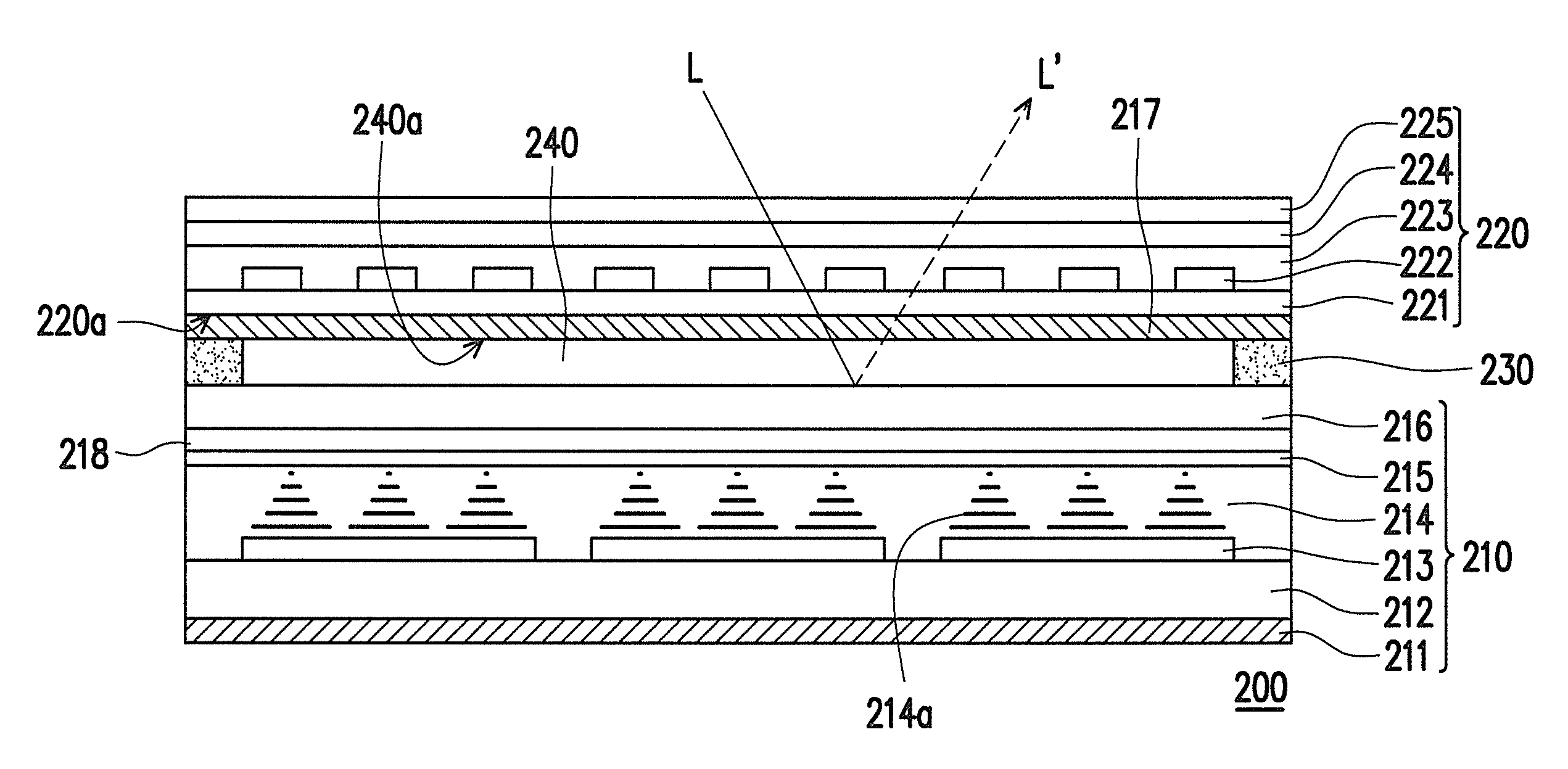
[0021]According to the touch display of the present invention, by setting the polarized plate at a side of the touch panel facing to the display unit, intensity of reflected light may be weakened and the contrast of the displayed image may be improved. More particularly, since the second polarized plated is set on the touch panel, not only the LCD with a built-in touch panel may normally display images, but also intensity of the light reflected by the air layer may be reduced. Moreover, by applying the second polarized plate and the quarter-wavelength plate, interference caused by the reflected light may be completely eliminated. Therefore, the LCD with a built-in touch panel may provide images with a good contrast and visibility.

Problems solved by technology

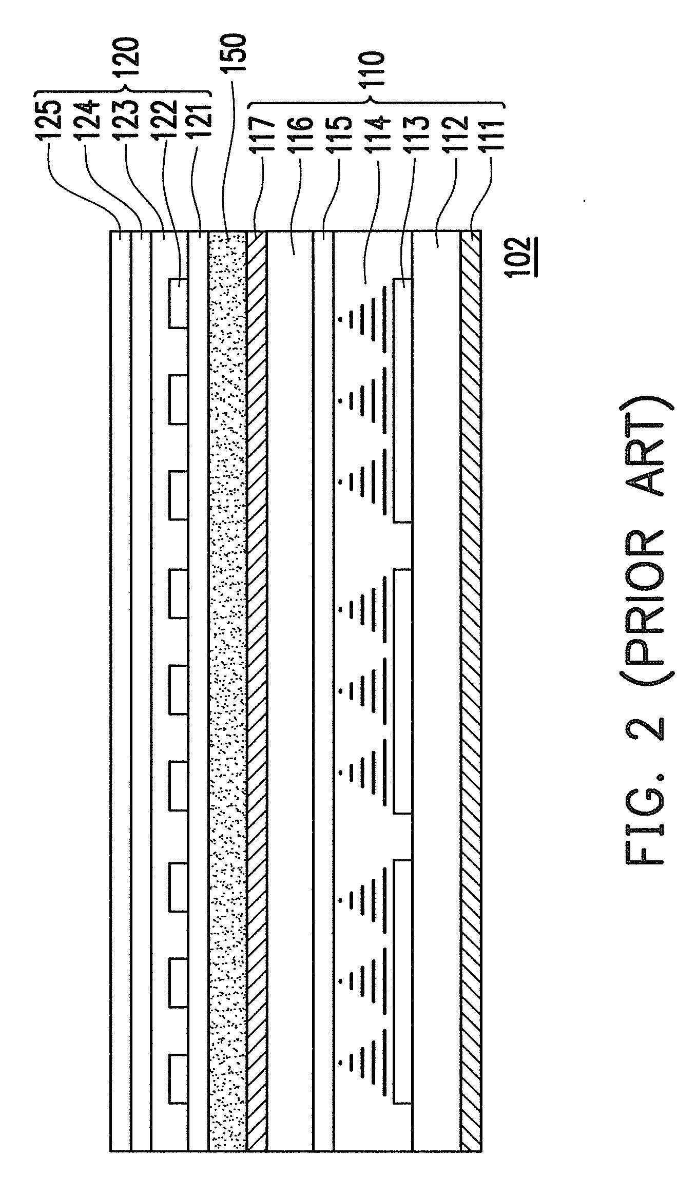
However, the optical adhesive 150 may have a poor reliability after long time utilization.
Moreover, during assembling, air bubbles may be generated in the optical adhesive 150, which may lead to an abnormal scattering of light.
Furthermore, utilization of the optimal adhesive 150 may have a problem of excessive overall thickness, and is uneasy to rework when sticking quality thereof is poor.
More particularly, if the touch panel 120 is damaged and the LCD panel 110 functions well, it is difficult to replace the touch panel 120.
However, cost of the antireflection film 160 is relatively high.

Method used


Image

  • Touch display, liquid crystal display with a built-in touch panel
  • Touch display, liquid crystal display with a built-in touch panel
  • Touch display, liquid crystal display with a built-in touch panel

Examples


Embodiment Construction

[0030]FIG. 4 is a schematic diagram illustrating an LCD with a built-in touch panel according to a preferred embodiment of the present invention. Referring to FIG. 4, the LCD 200 with a built-in touch panel includes an LCD unit 210, a touch panel 220 and a second polarized plate 217. The LCD unit 210 includes a lower substrate 212, an upper substrate 216, a liquid crystal layer 214 and a first polarized plate 211. The upper substrate 216 is disposed opposite to the lower substrate 212. The liquid crystal layer 214 is disposed between the lower substrate 212 and the upper substrate 216. The first polarized plate 211 is disposed on the lower substrate 212. The touch panel 220 is disposed opposite to the upper substrate 216. The second polarized plate 217 is disposed at a side 220a of the touch panel 220 facing to the LCD unit 210, and is located between the LCD unit 210 and the touch panel 220.

[0031]In an embodiment, the first polarized plate 211 has a first polarized direction, and t...


PUM


Abstract

A liquid crystal display (LCD) with a built-in touch panel includes an LCD unit, a touch panel and a second polarized plate. The LCD unit includes a lower substrate, an upper substrate, a liquid crystal layer and a first polarized plate. The upper substrate is disposed opposite to the lower substrate, and the liquid crystal layer is disposed between the lower substrate and the upper substrate. The first polarized plate is disposed on the lower substrate and has a first polarized direction. The touch panel is disposed opposite to the LCD unit. The second polarized plate having a second polarized direction is disposed on the touch panel and located between the LCD unit and the touch panel. An intensity of a reflected light occurred in the LCD with the built-in touch panel is relatively low, so that good contrast and visibility are obtained.

Description

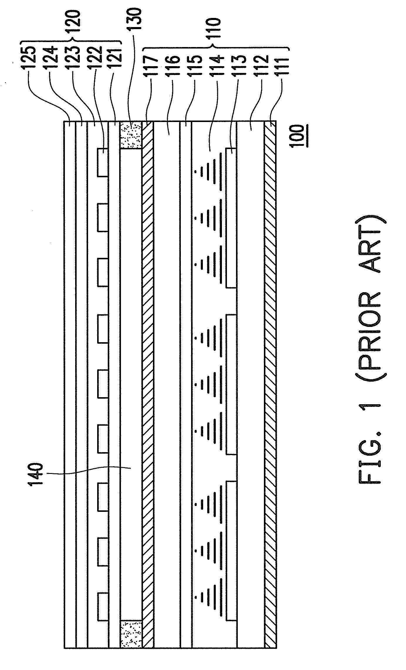
CROSS-REFERENCE TO RELATED APPLICATION[0001]This application claims the priority benefit of Taiwan application serial no. 97106638, filed on Feb. 26, 2008. The entirety of the above-mentioned patent application is hereby incorporated by reference herein and made a part of this specification.BACKGROUND OF THE INVENTION[0002]1. Field of the Invention[0003]The present invention relates to a touch display. More particularly, the present invention relates to a liquid crystal display (LCD) with a built-in touch panel having a good contrast and visibility.[0004]2. Description of Related Art[0005]FIG. 1 is a schematic diagram of a conventional LCD with a built-in touch panel. Referring to FIG. 1, the LCD 100 with a built-in touch panel includes an LCD panel 110 and a touch panel 120. The LCD panel 110 includes a first polarized plate 111, a lower substrate 112, an active device array 113, a liquid crystal layer 114, a common electrode layer 115, an upper substrate 116 and a second polarized...

Claims


Application Information

Patent Timeline
IPC IPC(8): G06F3/045G06F3/041
CPCG06F3/0412G02F1/13338G06F3/042G06F3/043G06F3/044G06F3/045
Inventor KUO, CHIEN-CHUNGCHI, CHUN-CHI
Owner WINTEK CORP
Learn More