Method for three dimensional seismic travel time tomography in transversely isotropic media

a technology of travel time and tomography, applied in the field of seismic data processing, can solve the problems of inaccurate pre-seismic depth migration, inability to accurately predict the position of seismic events in space, and inability to optimize the energy “focusing” after migration

Active Publication Date: 2009-08-27
PGS GEOPHYSICAL AS
View PDF4 Cites 35 Cited by
  • Summary
  • Abstract
  • Description
  • Claims
  • Application Information

AI Technical Summary

Problems solved by technology

However, it has been recognized that when the seismic velocities are affected by anisotropy, the results from prestack depth migration may not be accurate.
If anisotropy is ignored in migration processing, positioning of the seismic events in space will be incorrect and energy “focusing” after migration will not be optimum.
Performing 3D tomographic velocity estimation for VTI m...

Method used


Image

  • Method for three dimensional seismic travel time tomography in transversely isotropic media
  • Method for three dimensional seismic travel time tomography in transversely isotropic media
  • Method for three dimensional seismic travel time tomography in transversely isotropic media

Examples


Embodiment Construction

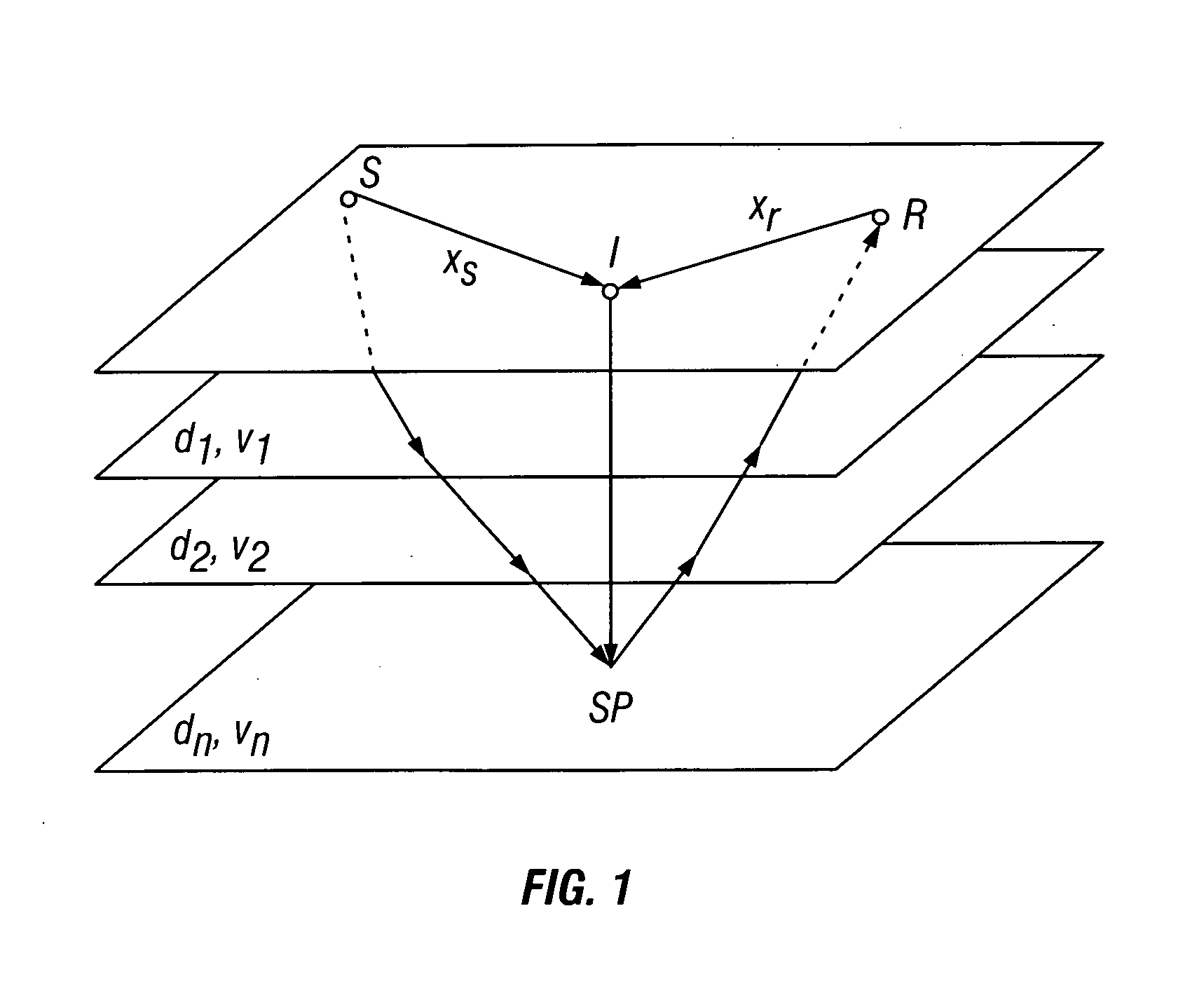
[0022]FIG. 1 shows a seismic energy travel path from a first source position S (geodetic position of a seismic energy source) to a first scatter point SP (a seismic imaging point in the subsurface corresponding to a particular geodetic position at the Earth's surface), and from the first scatter point SP to a first receiver position R (the geodetic position of a seismic receiver at the Earth's surface) The geodetic location at the Earth's surface directly above the first scatter point SP is designated as I, or the imaging location or “image point.”FIG. 1 shows the seismic energy travel path from only one source location, to the scatter point and back to only one receiver location. It should be understood that in a three dimensional (“3D”) seismic survey, in which there are a plurality of source positions and receiver positions, there is a seismic energy travel path from each source positions to each receiver positions through the scatter point SP. It is the object of the migration p...


PUM


Abstract

A method for estimating seismic velocities in vertically transversely isotropic media includes generating an initial estimate of vertical interval velocity and interval normal moveout velocity with respect to depth from seismic data. An initial estimate is generated of a first anisotropy parameter with respect to depth. The first anisotropy parameter is related to the interval normal moveout velocity and the interval vertical velocity. An initial estimate is generated with respect to depth of a second anisotropy parameter. The second anisotropy parameter is related to the first anisotropy parameter and an interval anelliptic parameter. A first tomographic inversion is performed with respect to the interval normal moveout velocity and the second anisotropy parameter at a constant value of the first anisotropy parameter until travel time differentials reach minimum values. Layer depths are adjusted with the initial estimate of vertical interval velocity. Using values of the second anisotropy parameter determined in the first tomographic inversion, a second tomographic inversion is performed of interval normal moveout velocity and the first anisotropy parameter with respect to depth. The adjusted layer depths, interval normal moveout velocities and interval vertical velocities are again adjusted and interval anelliptic parameters are calculated from the second tomographic inversion.

Description

CROSS-REFERENCE TO RELATED APPLICATIONS[0001]Not applicable.STATEMENT REGARDING FEDERALLY SPONSORED RESEARCH OR DEVELOPMENT[0002]Not applicable.BACKGROUND OF THE INVENTION[0003]1. Field of the Invention[0004]The invention relates generally to the field of seismic data processing. More particularly, the invention relates to methods for producing seismic images of the Earth's subsurface using prestack depth migration.[0005]2. Background Art[0006]Seismic surveying is used to evaluate structures of, compositions of, and fluid content of subsurface earth formations. A particular application for seismic surveying is to infer the presence of useful materials, such as petroleum, in the subsurface earth formations. Generally, seismic surveying includes deploying an array of seismic sensors at or near the Earth's surface, and deploying a seismic energy source near the sensors also at or near the surface. The seismic energy source is actuated and seismic energy emanates from the source, travel...

Claims


Application Information

Patent Timeline
IPC IPC(8): G01V1/28
CPCG01V1/28G01V2210/66G01V2210/626G01V1/303
Inventor MARTINEZ, RUBEN D.JIAO, JUNRU
Owner PGS GEOPHYSICAL AS
Why Eureka
Try Eureka