Seismic scattering P-P wave imaging method

A technology of seismic scattering and imaging methods, applied in seismic signal processing and other directions, can solve problems such as weathering, achieve the effects of improving signal-to-noise ratio, enriching geological information, and improving imaging accuracy

Inactive Publication Date: 2010-12-01
XI'AN PETROLEUM UNIVERSITY
View PDF0 Cites 8 Cited by
  • Summary
  • Abstract
  • Description
  • Claims
  • Application Information

AI Technical Summary

Problems solved by technology

There are insurmountable deficiencies and difficulties in the theoretical and practical application of traditional seismic imaging technology. Therefore, other processing technologies must be sought to improve or solve the problem of defects in the imaging effect of current seismic imaging technology, especially in areas with complex underground structures ( S

Method used


Image

  • Seismic scattering P-P wave imaging method
  • Seismic scattering P-P wave imaging method
  • Seismic scattering P-P wave imaging method

Examples


Embodiment 1

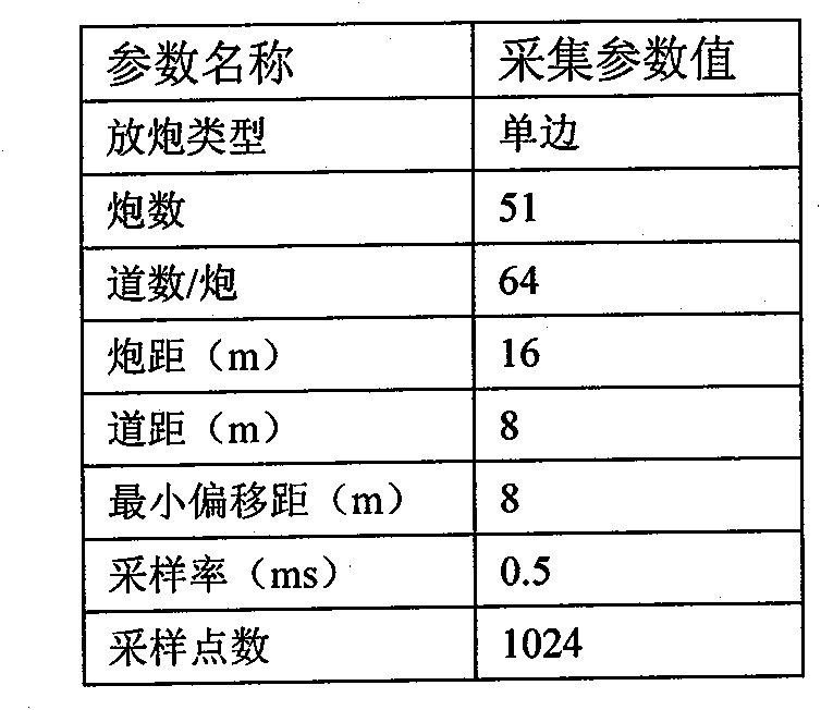
[0042] Take a fault model seismic data containing 51 shots, 64 traces per shot, and 1024 sampling points per trace as an example to illustrate the implementation steps of this example:

[0043] Step 1: Read the seismic data containing 51 shots, 64 traces per shot, and 1024 sampling points per trace into the two-dimensional array F, and load the observation system parameters into the original seismic data trace header, and according to the observation system and acquisition parameters to calculate the location and coordinates of scattering points;

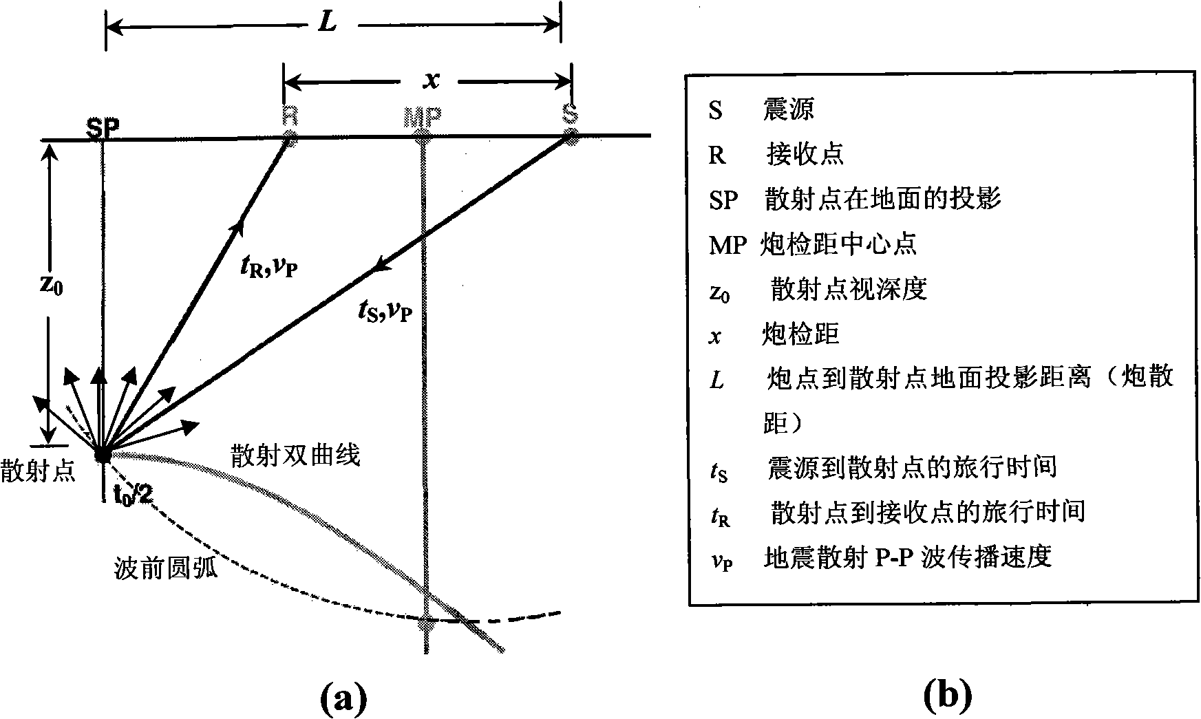
[0044] Step 2: According to the time-distance hyperbolic equation of the scattered wave, on the shot set, fix t 0i In the case of , the scattering hyperbolic trajectory is determined by the imaging velocity, and then the seismic scattering P-P wave normal time difference is calculated.

[0045] The time-distance hyperbolic equation of seismic scattering P-P wave:

[0046] t ji = ...

Embodiment 2

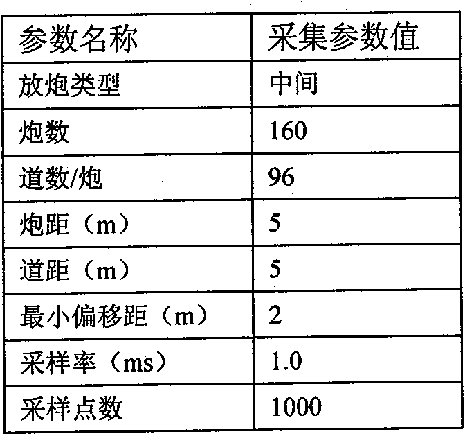
[0056] Take an actual seismic survey data containing 160 shots, 96 traces per shot, and 1000 sampling points per trace as an example to illustrate the implementation steps of this example:

[0057] Step 1: Read the seismic data containing 160 shots, 96 traces per shot, and 1000 sampling points per trace into the two-dimensional array F, and load the observation system parameters into the original seismic data trace header, and according to the observation system and acquisition parameters to calculate the location and coordinates of scattering points;

[0058] Step 2: According to the time-distance hyperbolic equation of the scattered wave, on the shot set, fix t 0i In the case of , the scattering hyperbolic trajectory is determined by the imaging velocity, and then the seismic scattering P-P wave normal time difference is calculated.

[0059] The time-distance hyperbolic equation of seismic scattering P-P wave:

[0060] t ji = ...


PUM


Abstract

The invention relates to a seismic scattering P-P wave imaging method which comprises the following steps: step 1: reading the seismic data into a two-dimensional array F, simultaneously loading observation system parameters into an original seismic data header, and calculating positions and coordinates of scattering points according to an observation system and acquisition parameters; step 2: according to the time-distance hyperbolic equation of scattering waves, under the condition of fixing t0i on a shot set, determining the scattering hyperbolic trace through the imaging speed, and then, calculating the seismic scattering P-P wave normal moveout; step 3: subtracting the seismic scattering P-P wave normal moveout from the seismic wave traveltime; step 4: calculating the weighted sum of the scattering amplitude of the hyperbolic trace from which the seismic scattering P-P wave normal moveout is subtracted on each shot-geophone distance, thereby realizing the seismic scattering P-P wave imaging; and step 5: outputting the imaging data in the seismic format. The invention has the characteristics of improving the stacking times of the horizontal stacking imaging technique and effectively improving the signal-to-noise ratio and the imaging precision.

Description

technical field [0001] The invention belongs to the technical field of seismic wave imaging processing, in particular to a seismic scattering P-P wave imaging method. technical background [0002] In actual seismic exploration, reflected waves are very limited in seismic wave components, and the propagation rules of reflected waves and other components of seismic waves are different. If the seismic waves of other components are treated with reflection theory, the imaging results obtained must be Inaccurate; in addition, the common center point (CMP) gather processing technology based on the time-distance hyperbolic theory of reflected waves is a set of processing technology developed for the horizontal layered uniform medium model. Strictly speaking, this technology is only applicable to horizontal Layered homogeneous medium, but in reality, this ideal situation hardly exists. There are insurmountable deficiencies and difficulties in the theoretical and practical applicatio...

Claims


Application Information

Patent Timeline
IPC IPC(8): G01V1/28
Inventor 沈鸿雁
Owner XI'AN PETROLEUM UNIVERSITY
Why Eureka
Try Eureka