
100 Gbit/s OFDM Optical Signal Generation

a technology of optical signal and gbit/s ofdm, which is applied in the field of 100 gbit/s ofdm optical signal generation, can solve the problems of not being able to generate 50 gbit/s ofdm and not being able to generate 100 gbit/s ofdm signal

Active Publication Date: 2009-08-27
NEC CORP
View PDF2 Cites 15 Cited by
  • Summary
  • Abstract
  • Description
  • Claims
  • Application Information

AI Technical Summary

Problems solved by technology

But due to the limited bandwidth of the analog to digital converter (A / D) and digital to analog converter (D / A), no 100 Gbit / s OFDM signal has been generated.
In this way, only 50 Gbit / s OFDM can be generated due to the limited bandwidth of an A / D converter.

Method used


Image

  • 100 Gbit/s OFDM Optical Signal Generation
  • 100 Gbit/s OFDM Optical Signal Generation
  • 100 Gbit/s OFDM Optical Signal Generation

Examples


Embodiment Construction

[0013]The invention is directed to a method for generating an over 100 Gbit / s OFDM signal due to both sidebands being employed.

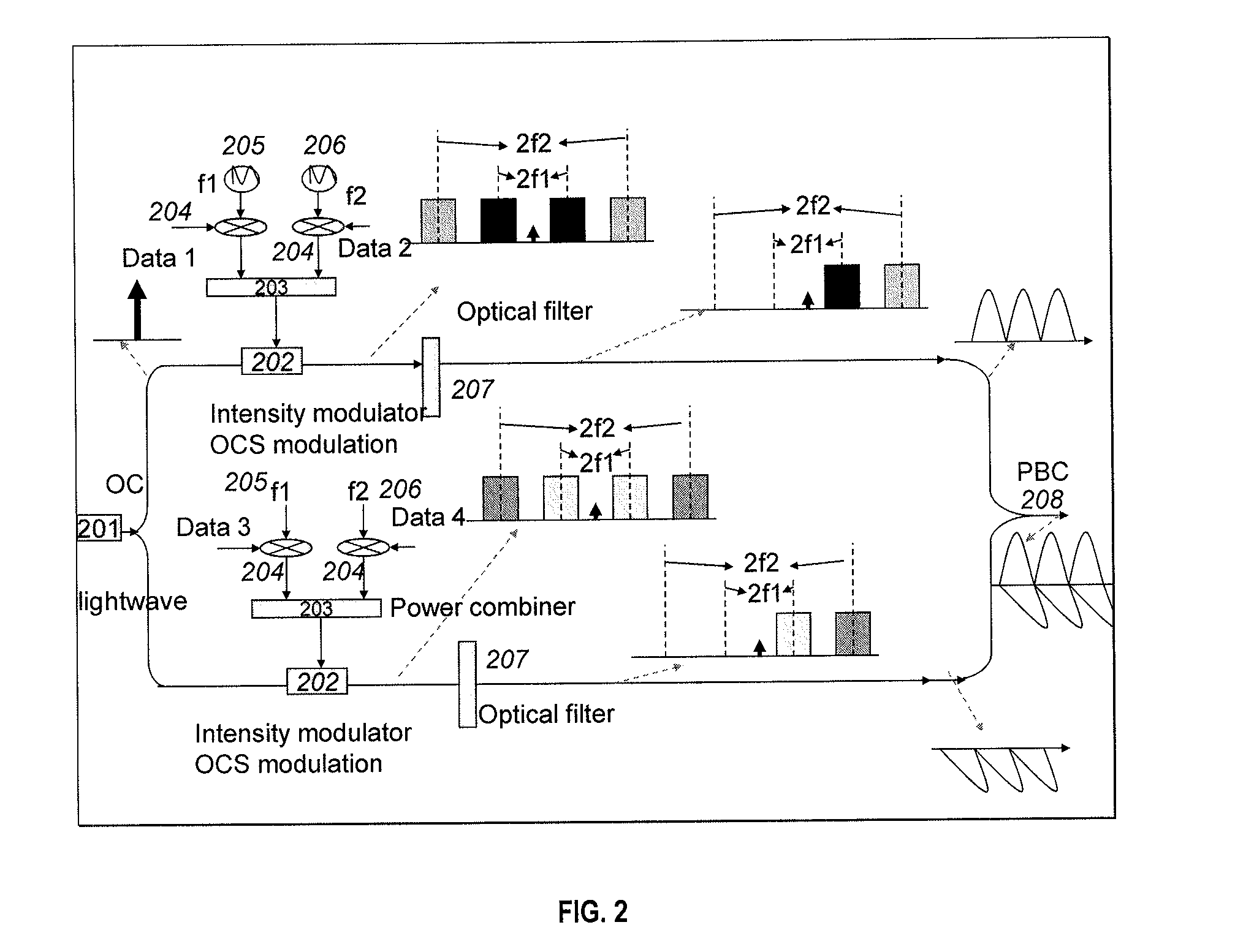
[0014]FIG. 3 is a diagram of an exemplary 100 Gbit / s OFDM optical signal generation for transmission, in accordance with the invention, with only one RF frequency. FIG. 4 is a diagram of an exemplary reception of 100 Gbit / s OFDM optical signal generated for transmission in accordance with the invention. FIG. 5 a diagram of a modification to the configuration of FIG. 3 to show 100 Gbit / s OFDM optical signal generation with two RF frequencies for transmission, in accordance with the invention.

[0015]The diagrams of FIGS. 3, 4 and 5 are exemplary configurations using the following optical and electrical components: lightwave source 301, 501, RF frequency 304, 505, 506; electrical mixer 303, 304, 504; optical coupler 306, 507; intensity modulator 302, 502; optical filter 305, 508; and optical polarization beam combiner 307, 509.

[0016]The lightwave 301, 501 can be...


PUM


Abstract

A method includes modulating lightwaves to provide first and second OFDM signal sidebands at a first polarization direction and first and second OFDM signal sidebands at a second polarization direction, and combining sidebands that are oppositely positioned and joined from the first and second OFDM signal sidebands at each polarization direction to provide a polarization multiplexing OFDM signal.

Description

[0001]This application claims the benefit of U.S. Provisional Application No. 61 / 030,346, entitled “Simultaneous Generation of Centralized Lightwaves and Double / Single Sideband Optical Millimeter-Wave Requiring Only Low frequency Local Oscillator Signals for radio-Over-Fiber Systems”, filed on Feb. 21, 2008, the contents of which is incorporated by reference herein.BACKGROUND OF THE INVENTION[0002]Optical networks designed for Ethernet traffic are becoming more important as the dominance of data over voice services increases. Work in both standards committees and research communities have targeted the transport of 100-Gbit / s Ethernet (100 GE) over wide area networks. Orthogonal frequency division multiplexing (OFDM) is a good transmission format for realizing 100 Gbit / s signal transmission. In recent years, a number of different alternatives have OFDM as a promising method to eliminate the need for optical dispersion compensation in long-haul transmission links. Fiber-optic OFDM sys...

Claims


Application Information

Patent Timeline
IPC IPC(8): H04J14/06
CPCH04B10/5165H04B10/532H04J14/002H04B10/548H04L5/0014H04L27/2627H04L27/2697H04J14/06
Inventor YU, JIANJUNWANG, TING
Owner NEC CORP
Learn More