Optical receiver systems and methods for polarization demultiplexing, pmd compensation, and dxpsk demodulation

a receiver and optical technology, applied in the field of optical receivers, can solve the problems of limiting the utilization of the overall transmission system in wavelength division multiplexed (wdm) systems, high data rates are being pushed towards ever increasing speeds, and direct binary modulation schemes have poor spectral efficiency, so as to reduce the number of delay line demodulators and reduce the cost

Active Publication Date: 2009-04-23
CIENA
View PDF11 Cites 26 Cited by
  • Summary
  • Abstract
  • Description
  • Claims
  • Application Information

AI Technical Summary

Benefits of technology

[0010]In various exemplary embodiments, the present invention provides a simplified optical receiver architecture capable of tracking and demultiplexing polarization-multiplexed signals, dynamically compensating for PMD using a variety of polarization controller technologies, and reducing the number of delay line demodulators by two for both DPSK and DQPSK modulation. Once polarization is controlled at the first stage of the cascaded system of the present invention, subsequent stages can be simplified and cost reduced. This approach requires careful consideration of polarization through the complete receiver optical chain.

Problems solved by technology

However, these high data rates are being pushed towards ever increasing speeds due to rapid growth in networks.
Disadvantageously, direct binary modulation schemes have poor spectral efficiency which limits overall transmission system utilization in wavelength division multiplexed (WDM) systems.
PMD is a generally deleterious effect experienced by high-bit rate optical signals as they propagate in fibers.
At some point, there is sufficient delay that accumulates between the modes such that the signal arriving at the receiver looks like two streams with different arrival times. The received signal experiences dual-path interference.
However, the impairment experienced by the data signal is proportional to the bit rate, as the bit period is shortened.
PMD poses a particular problem with polarization multiplexing as data is carried on orthogonal polarizations, and PMD destroys the orthogonality and induces polarization cross-talk.
Disadvantageously, conventional transmission schemes have increased complexity associated with receiver design.
Finally, DxPSK modulation requires a separate Delay Demodulator 20,22 for each Quadrature and polarization (i.e., two for DPSK and four for DQPSK), which correspondingly increases system cost.
Treating each stage as an independent PMD Compensator, followed by PM demultiplexing, followed by DxPSK demodulation is rather expensive, inefficient, and would require faster control loops at each stage.

Method used


Image

  • Optical receiver systems and methods for polarization demultiplexing, pmd compensation, and dxpsk demodulation
  • Optical receiver systems and methods for polarization demultiplexing, pmd compensation, and dxpsk demodulation
  • Optical receiver systems and methods for polarization demultiplexing, pmd compensation, and dxpsk demodulation

Examples


Embodiment Construction

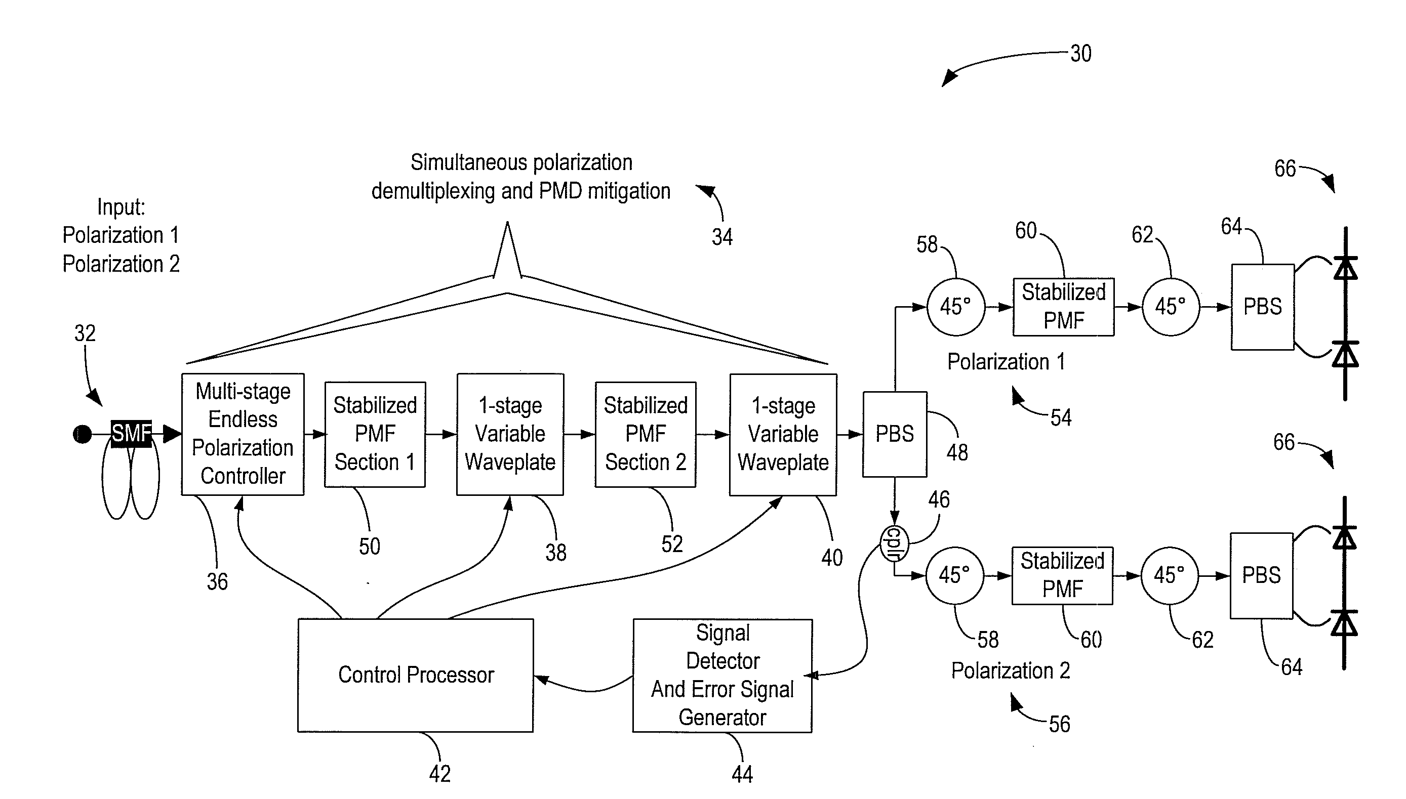
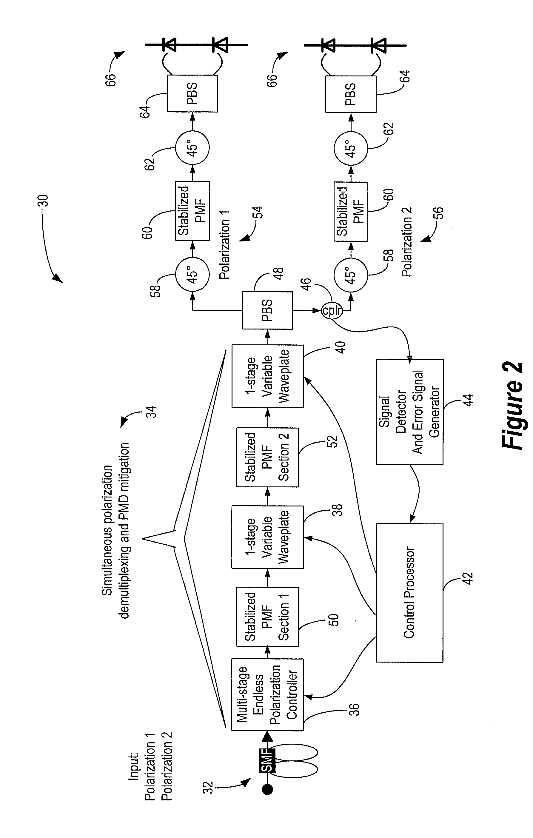
[0024]In various exemplary embodiments, the present invention provides a simplified optical receiver architecture capable of tracking and demultiplexing polarization-multiplexed signals, dynamically compensating for PMD using a variety of polarization controller technologies, and reducing the number of delay line demodulators by two for both DPSK and DQPSK modulation. Once polarization is stabilized at the first stage of the cascaded system of the present invention, subsequent stages can be simplified and cost reduced.

[0025]The present invention stabilizes polarization maintaining fiber (PMF) sections such that phase variations stay well within a single 2π period. Thus, the present invention only requires a single, fully-arbitrary polarization controller, and subsequent controllers can be implemented as single-stage adjustable waveplates with a well-defined axis orientation. Alternatively, the present invention contemplates using crystal-based differential polarization delays or the...


PUM


Abstract

A simplified optical receiver architecture capable of tracking and demultiplexing polarization-multiplexed signals, dynamically compensating for PMD using a variety of polarization controller technologies, and reducing the number of delay line demodulators by two for both DPSK and DQPSK modulation is illustrated. Once polarization is stabilized at the first stage of the cascaded system of the present invention, subsequent stages can be simplified and cost reduced.

Description

FIELD OF THE INVENTION[0001]The present invention relates generally to optical receivers, and more particularly, to systems and methods for a simplified optical receiver architecture capable of tracking and demultiplexing polarization-multiplexed signals, dynamically compensating for Polarization Mode Dispersion (PMD) using a variety of polarization controller technologies, and reducing the number of delay line demodulators by two for both Differential Phase Shift Keying (DPSK) and Differential Quadrature Phase Shift Keying (DQPSK) modulation.BACKGROUND OF THE INVENTION[0002]Conventional fiber optic communication systems are well-developed for transmitting high-data rate signals, such as 10 Gbps and 40 Gbps signals. However, these high data rates are being pushed towards ever increasing speeds due to rapid growth in networks. For example, current standards bodies (e.g., IEEE) are considering data rates of 100 Gbps, which would require ever higher transmission rates (i.e., approximat...

Claims


Application Information

Patent Timeline
Patent Type & Authority Applications(United States)
IPC IPC(8): H04J14/06
CPCH04B10/2569H04J14/06H04B10/677
Inventor FRANKEL, MICHAEL
Owner CIENA
Why Eureka
Try Eureka