System and method for analyzing an impedance course

Active Publication Date: 2009-08-27
BIOTRONIK SE & CO KG
View PDF12 Cites 24 Cited by
  • Summary
  • Abstract
  • Description
  • Claims
  • Application Information

AI Technical Summary

Benefits of technology

[0025]The invention is based on the object of specifying a device and a method that avoids the disadvantages of the prior

Problems solved by technology

However, in contrast to the known methods, no absolute impedance values are used for the detection of the incr

Method used


Image

  • System and method for analyzing an impedance course
  • System and method for analyzing an impedance course
  • System and method for analyzing an impedance course

Examples


Embodiment Construction

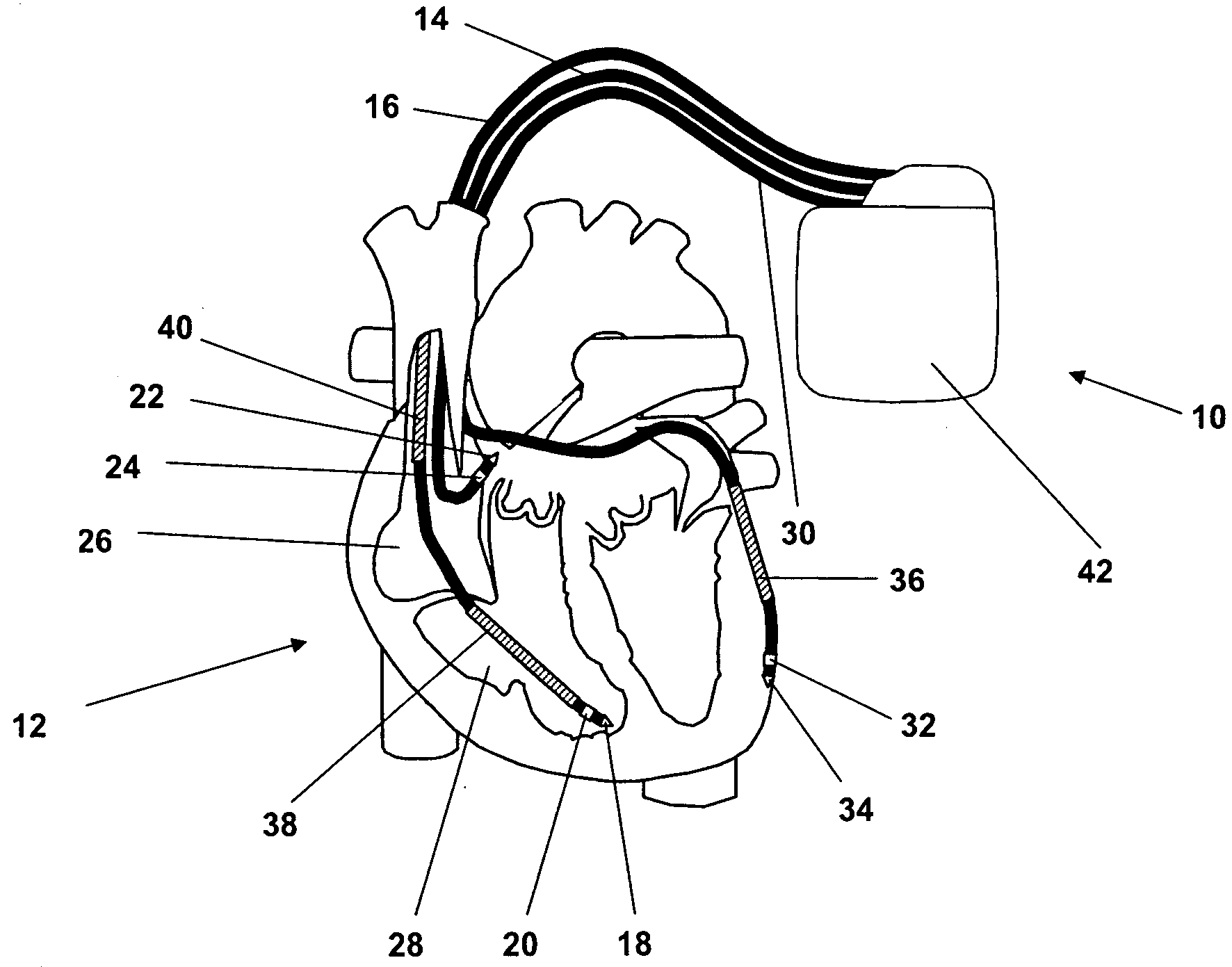
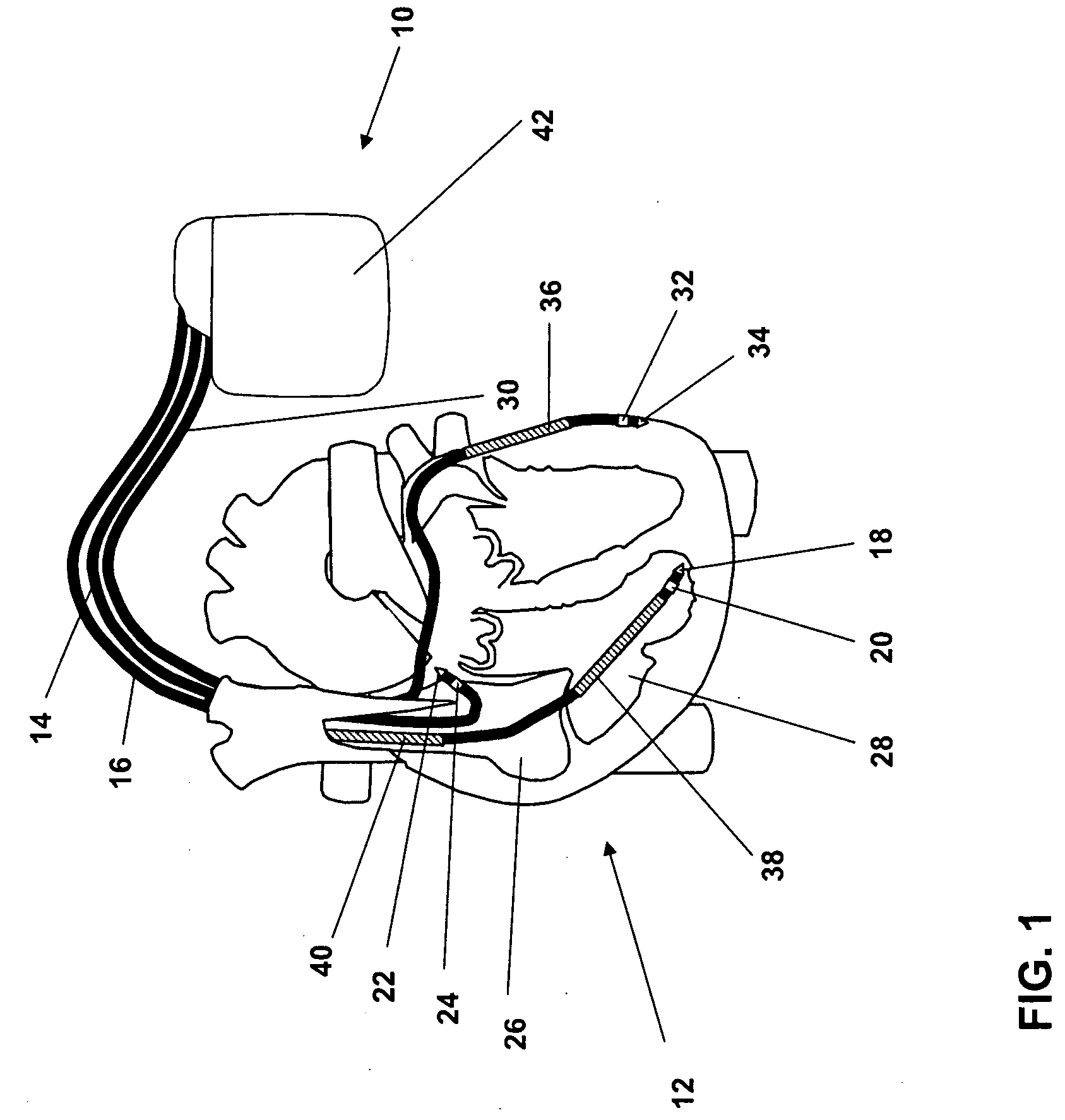
[0040]FIG. 1 shows an implant 10 in the form of a biventricular three-chamber cardiac pacemaker and cardioverter / defibrillator (ICD). Three electrode lines are connected thereto, namely a right-atrial electrode line 14, a right-ventricular electrode line 16, and a left-ventricular electrode line 30. In the implanted state, the right-atrial electrode line 14 terminates in the right atrium 26 of a heart 12. The right-ventricular electrode line 16 terminates in the right ventricle 28 of the heart 12 and the left-ventricular electrode line 30 extends via the coronary sinus of the heart 12 up to the left ventricle of the heart.

[0041]The right-atrial electrode line 14 carries a right-atrial tip electrode 22 on its distal end and a right-atrial ring electrode 24 at a short distance therefrom. In a similar way, the right-ventricular electrode line 16 carries a right-ventricular tip electrode 18 on its distal end and a right-ventricular ring electrode 20 at a short distance therefrom. A left...


PUM


Abstract

A system which generates a warning signal in the event of looming pulmonary edema and/or looming decompensation. The system has an impedance detection unit for determining impedance values, which represent a transthoracic impedance course, and an impedance analysis unit (78), which is connected to the impedance detection unit. The impedance analysis unit (78) is implemented to determine the degree of modulation for a particular impedance course detected by the impedance detection unit.

Description

[0001]This application takes priority from German Patent Application DE 10 2008 010 651.8, filed 22 Feb. 2008, the specification of which is hereby incorporated herein by reference.BACKGROUND OF THE INVENTION[0002]1. Field of the Invention[0003]The invention relates to an implant having an impedance detection unit for determining a transthoracic impedance course and an impedance analysis unit, which is connected to the impedance detection unit and analyzes the impedance course, as well as a system and a method for analyzing the impedance course. The analysis of the impedance course is performed in each case with the goal of recognizing a decompensation as early and precisely as possible.[0004]2. Description of the Related Art[0005]In patients who suffer from cardiac insufficiency, acute worsening of their state may occur at irregular intervals, connected with a complete collapse of performance capability, respiratory distress, and fear of suffocation. In this case, immediate hospita...

Claims


Application Information

Patent Timeline
IPC IPC(8): A61B5/08A61N1/362
CPCA61B5/0535A61N1/37258A61N1/36521A61B5/0809
Inventor SKERL, OLAFLIPPERT, MICAHELCZYGAN, GERALDPAULE, STEFAN
Owner BIOTRONIK SE & CO KG
Why Eureka
Try Eureka