Eureka AIR delivers breakthrough ideas for toughest innovation challenges, trusted by R&D personnel around the world.

Wig and method of manufacturing the same

Inactive Publication Date: 2009-09-03
UNIHAIR COMPANY LIMITED
View PDF3 Cites 21 Cited by
  • Summary
  • Abstract
  • Description
  • Claims
  • Application Information

AI Technical Summary

Benefits of technology

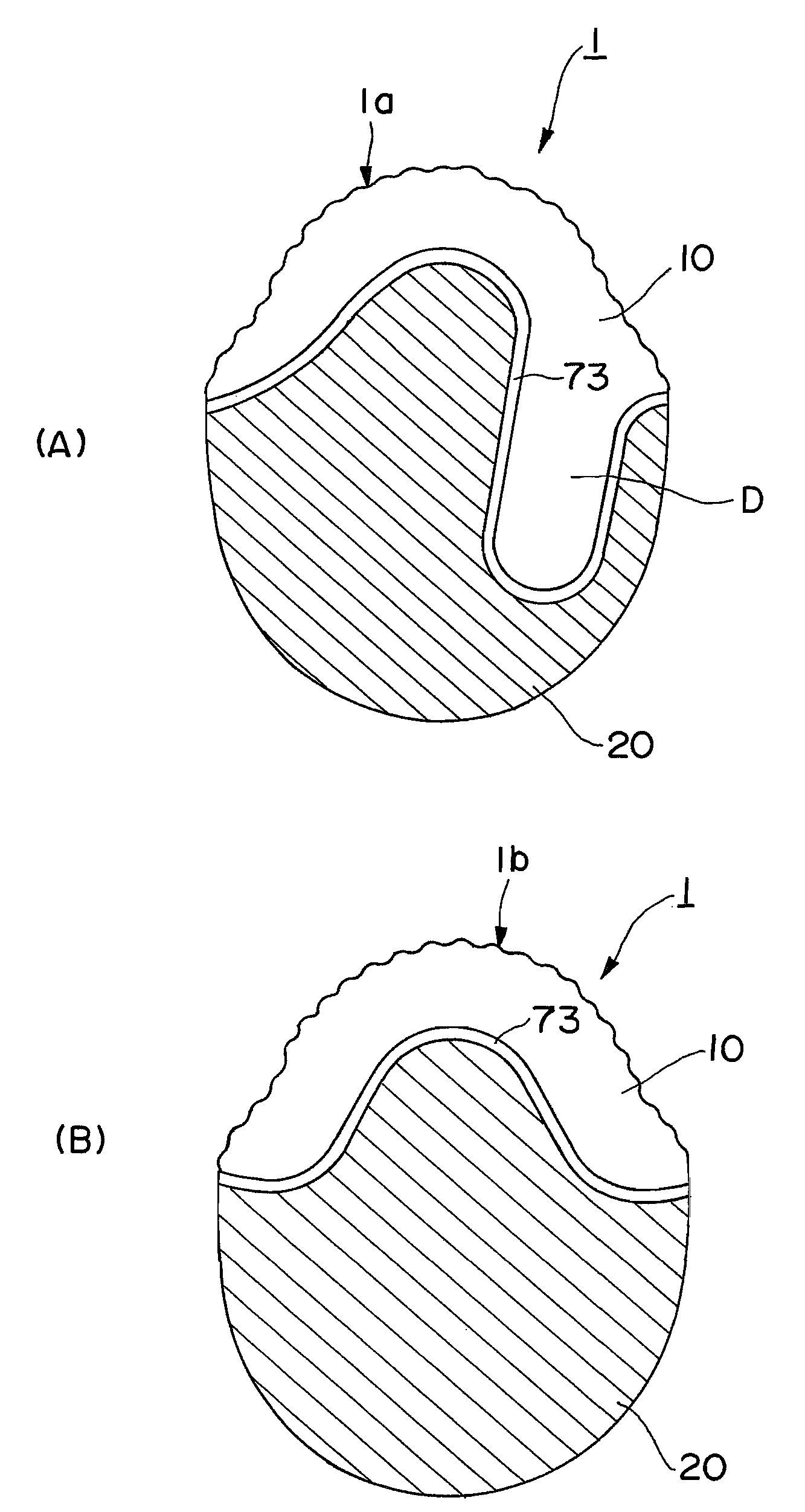
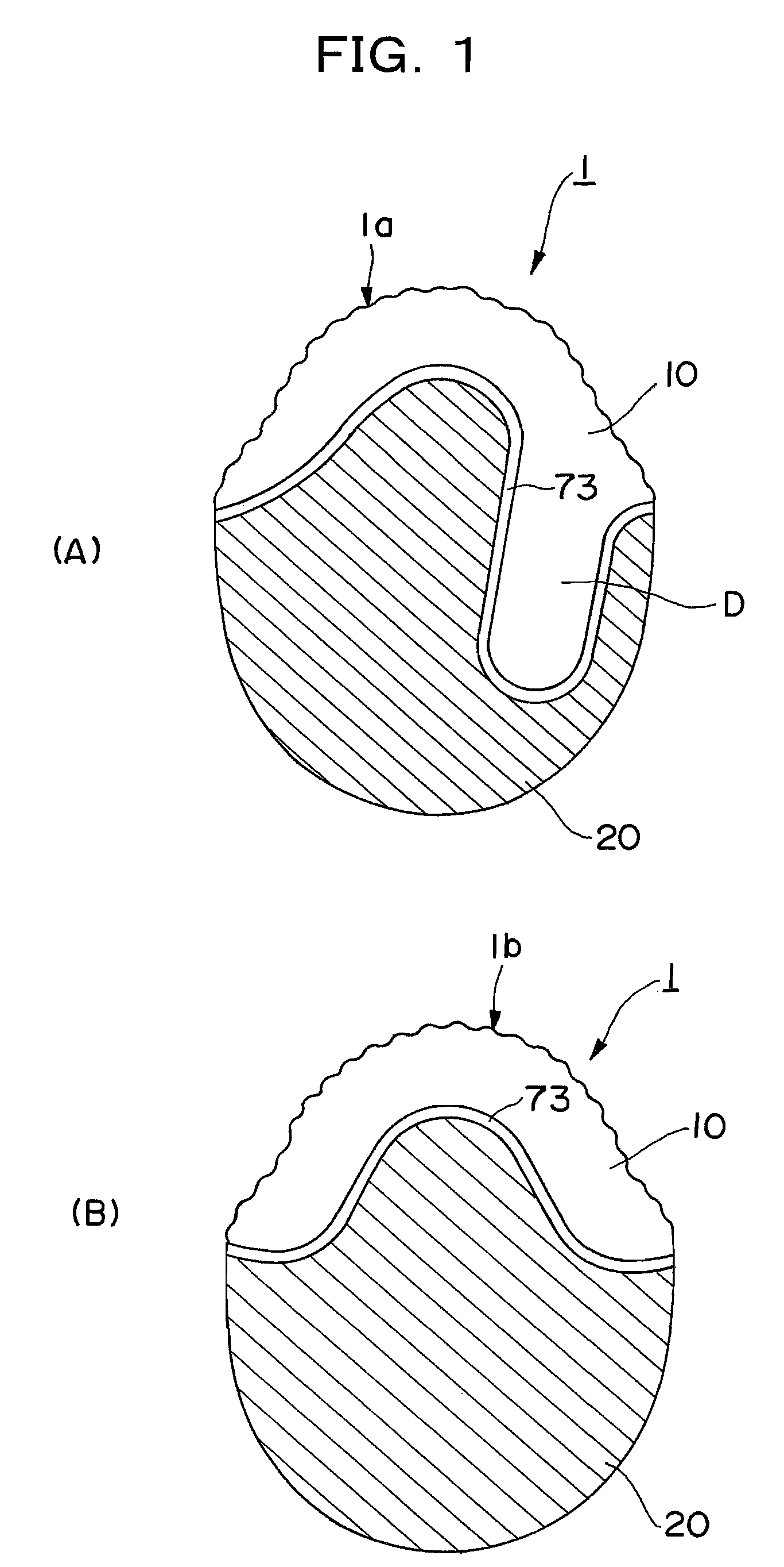
[0027]According to a wig and a method of manufacturing the same in accordance with the present invention, a wig base is constituted by combining and connecting the artificial skin the front edge of which is located at the position in the front portion of the wig base corresponding to the hairline of the wearer's forehead and the cap member formed to a net type similar to the wearer's head in the rear portion positioned behind said front portion. Therefore, the wig can be provided, wherein the wig base fits well the wearer's head, and the ultra-thin artificial skin of high camouflaging effect at the hairline of the forehead can be repeatedly bonded and repeeled.
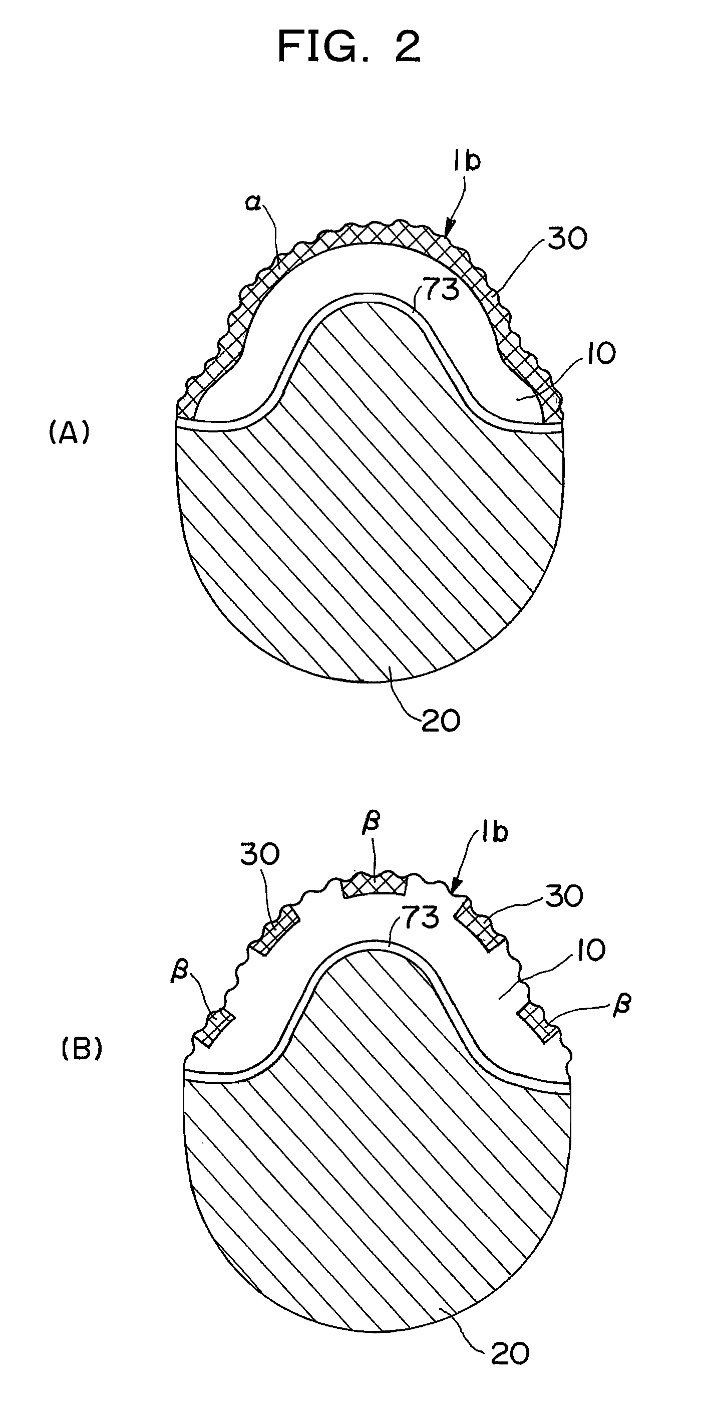
[0028]The surface side of the ultra-thin artificial skin provided at the hairline of the wig wearer's forehead is deglossed, and further the front edge of the ultra-thin artificial skin is wave-shaped, thereby the exposure of the wig can be further prevented. Also, after hair is attached to the wig base, an adhesive is coated on to the whole reverse side or at least a part of the end region including the front edge of said artificial skin for bonding the ultra-thin artificial skin to the head, thereby the wig can be provided which can further enhance the camouflaging effect at the hairline of the forehead.
[0029]One side of said adhesive layer is given a hair-fixing function to fix a stitch portion of the hair attached by penetrating to the reverse side of the artificial skin, and the other side of the adhesive layer to be attached to the scalp is given a repeelable function from the scalp. Since the adhesive is constituted of a single layer providing a hair-fixing function and a repeelable function from the scalp, the wig is made thin and light.

Problems solved by technology

As the result, the pattern of the pre-determined head shape is deformed, thereby a natural feeling can not be brought about.
Also, the fixed portion between the attaching net and the wig base becomes thickened, and the periphery of the wig base can not provide a natural feeling.

Method used


Image

  • Wig and method of manufacturing the same
  • Wig and method of manufacturing the same
  • Wig and method of manufacturing the same

Examples


example

[0143]Explanation is made of the example of the method of manufacturing the wig in accordance with the embodiment of the present invention.

[0144]As a first step, the solution in which an urethane elastomer was dissolved in DMF and MEK and an antifungal agent was incorporated was coated on to a plaster pattern of a wig wearer's head shape prepared in advance, and dried at heating temperature 60° C. for one hour. Further on said plaster pattern, the urethane elastomer solution of the concentration lower than the previous urethane elastomer solution was coated, dried for 30 minutes at heating temperature 60° C. to form the ultra-thin artificial skin material 11 of about 0.07 mm thickness.

[0145]As a second step, into the solution in which an urethane elastomer was dissolved in DMF and MEK and an antifungal agent was incorporated, powdery silica (average particle diameter 3.1 μm to 4.1 μm) as a deglossing agent 6, an ultraviolet absorber, and an antioxidant were further incorporated to p...


PUM


Abstract

In a wig 1, comprising wig bases 1a and 1b, and hair 12 attached to the wig base, the wig base is constituted with a front portion made of an artificial skin 10 of which a front edge is provided to a wig wearer's forehead, and a rear portion connected to the front portion, composed with a cap member having a shape similar to a wig wearer's head shape, the front portion has an artificial skin material 11 and an adhesive layer 30, wherein the adhesive layer 30 has a function to fix a stitch portion of hair by unpeelably adhering to a reverse side of the artificial skin material, and a function of a repeated bonding and peelable pressure-bonding to a scalp.

Description

TECHNICAL FIELD[0001]The present invention relates to a wig to cover at least a part of a head from a hairline to a back of the head and a method of manufacturing the same, and especially to the wig wherein the camouflage effect is improved on the front edge of the wig corresponding to the hairline of the wig wearer's forehead portion, and a method of manufacturing the same.BACKGROUND ART[0002]A wig to wear when head hair becomes thin is heretofore provided with a wig base made of an artificial skin which is made of synthetic resin, a mesh-like net, or combination of the artificial skin and the net, and is manufactured by forming the wig base to a wearer's head shape as far as possible, and attaching human or artificial hair thereon.[0003]Incidentally, hair losing is generally known to proceed by retreating of the hairline of the forehead. Therefore, in case to wear a wig, the front edge of the wig must be exactly fitted to the position corresponding to the wearer's ordinary or gene...

Claims


Application Information

Patent Timeline
IPC IPC(8): A41G3/00
CPCA41G3/00A41G3/0075A41G3/0041A41G5/00
Inventor SATO, TAKASHIMARUYAMA, SHIN-ICHIKONDO, YASUHIROOGAWA, YOSHIESUGAI, HIROKO
Owner UNIHAIR COMPANY LIMITED
Why Eureka
Eureka Blog
Learn More