Electromagnetic contactor

a contactor and electromagnetic technology, applied in the field of electromagnetic contactors, can solve the problems of increasing the size of the apparatus, difficult to reconcile all these criteria, and increasing the size of the contactor, so as to reduce the contact area, reduce the shock, and reduce the effect of the conjunction tim

Active Publication Date: 2009-09-03
ABB (SCHWEIZ) AG
View PDF6 Cites 9 Cited by
  • Summary
  • Abstract
  • Description
  • Claims
  • Application Information

AI Technical Summary

Benefits of technology

[0038]The electronic card makes it possible to limit the shocks during the inrush phase, and therefore to considerably reduce the contact areas of the two armatures without exposing the magnetic circuit to premature wear, and without increasing the conjunction time.
[0039]It is therefore possible to use the conical “progressive gap” shape that reduces the ampere-turns needed at inrush, since the effective gap is smaller than the actual travel of the moving core.
[0040]The combination of the above features consequently makes it possible to obtain a contactor of lower inrush power and of lower overall volume, equivalent to a contactor of the same range but not having a low inrush power.

Problems solved by technology

The use of these technologies usually results in an increase in the size of these contactors compared with the AC drive version.
However, it turns out that this solution imposes a specific and limiting arrangement of the supply terminals of the card, thereby again resulting in an increase in the size of the apparatus when this solution is applied on various current ratings of contactors.
However, it is difficult to reconcile all these criteria.
Such an arrangement cannot be envisioned for a contactor intended to be positioned on a support rail by fastening means placed to the rear of the coil.

Method used


Image

  • Electromagnetic contactor
  • Electromagnetic contactor
  • Electromagnetic contactor

Examples


Embodiment Construction

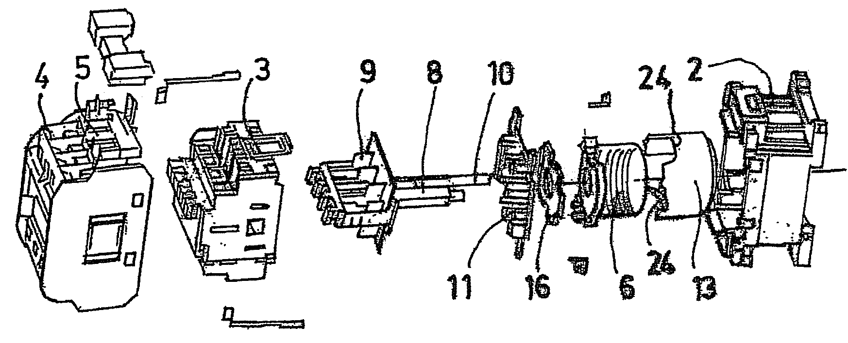
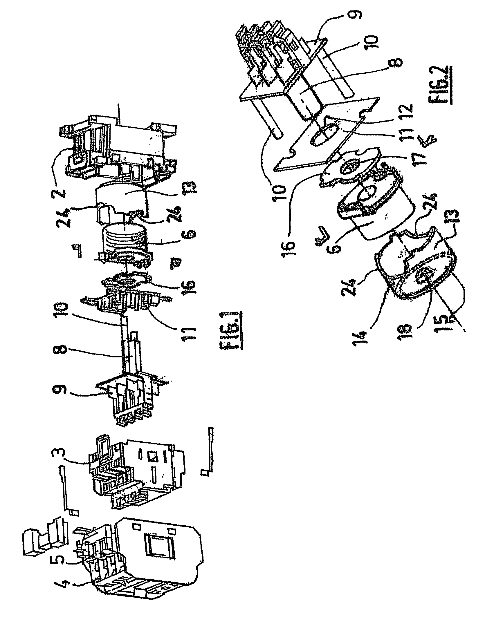
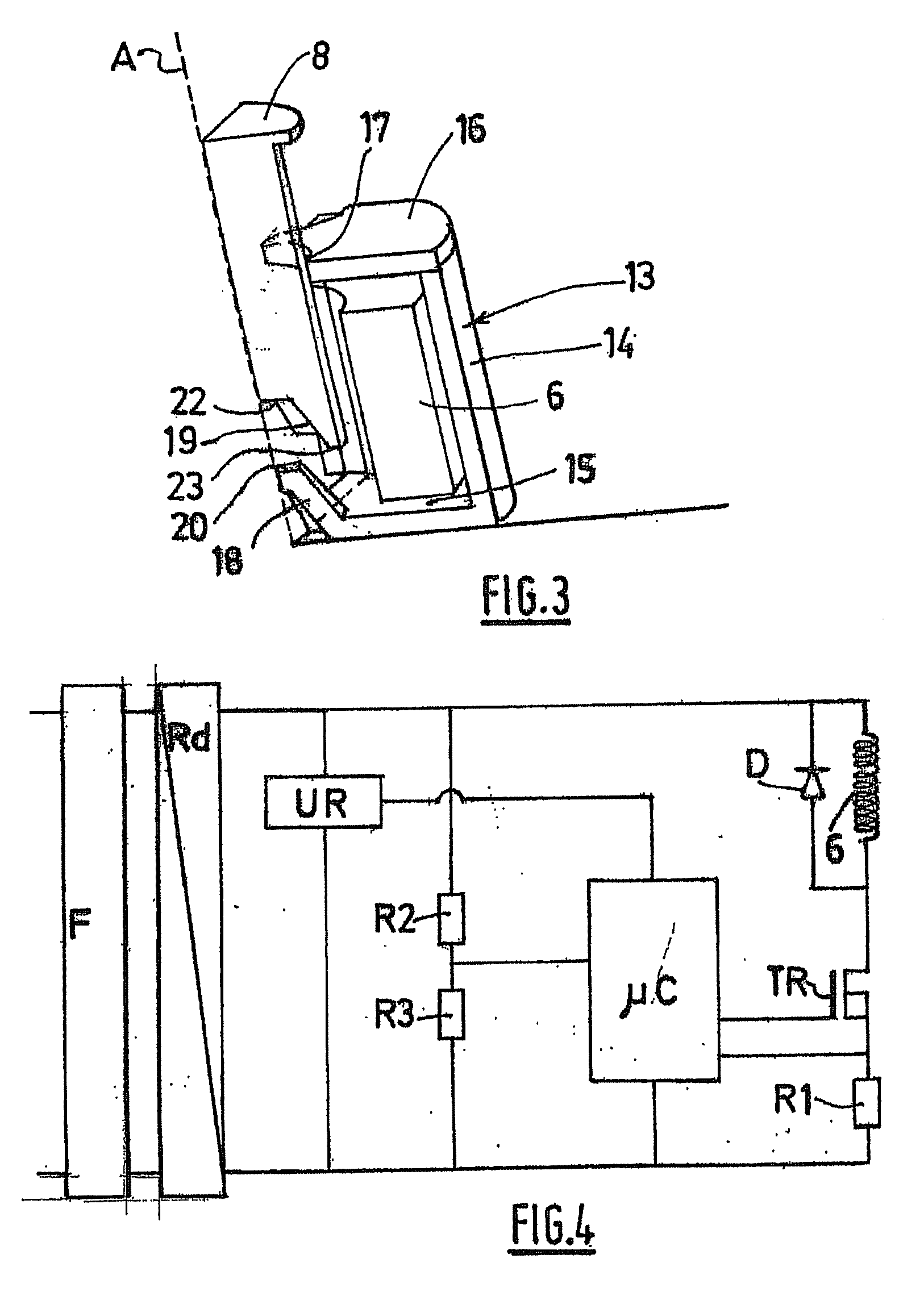
[0069]According to one embodiment, shown in FIGS. 1 to 4, an electromagnetic contactor according to the invention comprises an insulating case having a rear part 2, intended to be fastened to a support, and a front part 3, intended to be fastened to the rear part 2. Fixed contacts (not shown) are fastened to the front part 3 of the case. The insulating case also includes a terminal block 4 intended to be fastened above the front part and comprising connection terminals 5 intended to be connected to the fixed contacts.

[0070]The parts of the case form a housing in which the following are accommodated:[0071]a coil 6 for generating a magnetic field, said coil being fastened to the case; and[0072]a magnetic circuit having a fixed part 7 relative to the case and a moving part 8 relative to the case.

[0073]A moving-contact holder 9 is mounted so as to be fastened to the moving part 8 of the magnetic circuit.

[0074]The contact holder 9 comprises moving contacts, which are intended to be in co...


PUM


Abstract

electromagnetic contactor comprising a winding (6) for generating a magnetic field, a magnetic circuit comprising a stationary portion (7) and a mobile portion (8), and an electronic board (11) comprising means of controlling the power supply to the winding (6), the electronic board (11) being arranged horizontally above the stationary portion (7) of the magnetic circuit. The mobile portion (8) passes through the electronic board (11) via an opening (12) in the board and slides into the winding, the contactor comprising an insulating casing including a rear portion intended to be fastened onto a support.

Description

TECHNICAL FIELD OF THE INVENTION[0001]The invention relates to an electromagnetic contactor. In particular, the invention relates to an electromagnetic contactor intended to be fastened to a support rail, in contact with other electrical appliances.BRIEF SUMMARY OF THE INVENTION[0002]As is known, an electromagnetic contactor comprises:[0003]a coil for generating a magnetic field; and[0004]a magnetic circuit having a fixed part and a moving part.[0005]Elastic means are provided for keeping the fixed and moving parts apart in the absence of power supplied to the coil.[0006]In general, the electrical operation of a contactor may be described in two separate phases.[0007]During a first, inrush phase, when the coil is supplied with current, the magnetic circuit tends to be closed, the moving part moving toward the fixed part until these two parts are in contact. During this phase, a large amount of power is needed so as to overcome the initial gap and to move the moving part against the ...

Claims


Application Information

Patent Timeline
Patent Type & Authority Applications(United States)
IPC IPC(8): H01H9/02
CPCH01H50/021H01H50/546H01H50/20
Inventor LEFEBVRE, BRUNO
Owner ABB (SCHWEIZ) AG
Why Eureka
Try Eureka