Eureka AIR delivers breakthrough ideas for toughest innovation challenges, trusted by R&D personnel around the world.

Device for retaining and releasing appendages

a technology for retaining and releasing devices, applied in the field of aerospace, can solve problems such as large geometrical defects of tie rods, generating dynamic defects, and inclination or delocalization defects, and achieve the effect of limiting shocks and simple and robust solutions

Active Publication Date: 2020-07-28
THALES SA
View PDF5 Cites 0 Cited by
  • Summary
  • Abstract
  • Description
  • Claims
  • Application Information

AI Technical Summary

Benefits of technology

[0010]The invention proposes a simple and robust solution making it possible to limit the shocks caused by the relaxation of the tie rod at the same time as making it possible to use conventional tie rods without worrying about their thermal properties.
[0019]an actuator of the component making it possible to modify a characteristic dimension of the component along the axis between two values, the component producing a tension in the tie rod for the first of the two values and the tension in the tie rod being reduced for a second of the two values, the actuator being independent of the mechanism.
[0021]Thus the component has no predefined position between the mechanism and the end piece. This independence allows complete freedom in terms of the positioning of the component.

Problems solved by technology

However, it is known that in this type of device the tie rod can have large geometrical defects, in particular if the number of stacked elements is large.
The geometrical defects may be defects of inclination or of delocalization, for example.
These geometrical defects can generate dynamic defects reflected in radial forces or moments exerted at the ends of the tie rod.
Failure to take account of these defects can generate serious malfunctions, up to non-deployment of the spacecraft appendages, and therefore possibly implying failure of the mission.
Another known problem lies in the shock that may be produced on releasing the tie rod.
Now, at the moment of its release, the tie rod is in a stressed state and its sudden release can cause shocks that can degrade the spacecraft appendages or the satellite itself.
There is a two-fold problem in the context of some present-day devices.
Thereafter, the tie rod being under tension before it is released, its sudden release, already referred to, can cause deterioration at the level of the spacecraft appendages or the supporting structure.
However the “low shock” capability of these nuts is applicable only to triggering the release of the tie rod and not the release of the appendages themselves.
In fact, the geometrical defects of the tie rod are not really compensated and, in particular if the tie rod is of large size, there continues to be a sudden relaxation of the tie rod that can generate a shock that is sometimes intense, the tie rod striking the spaced appendages.
This solution has the disadvantage of limiting the choice of the materials from which the tie rod can be made.
In fact, the required thermal expansion may be incompatible with the mechanical strength necessary to fulfil the function of retaining the appendages, notably during the launch phase in which the satellite is subjected to high levels of vibration.
Moreover, the tie rod may be very long and it is necessary to heat it over its entire length to expand it.
The implementation of the heater over the entire length of the tie rod is a complicated process.

Method used


Image

  • Device for retaining and releasing appendages
  • Device for retaining and releasing appendages
  • Device for retaining and releasing appendages

Examples


Embodiment Construction

[0038]The following description relates to a satellite and to the deployment of its appendages. It is clearly understood that the invention is not limited to the aerospace field and may be used in other fields where appendages can be deployed. These may be terrestrial antennas, underwater sensors, etc.

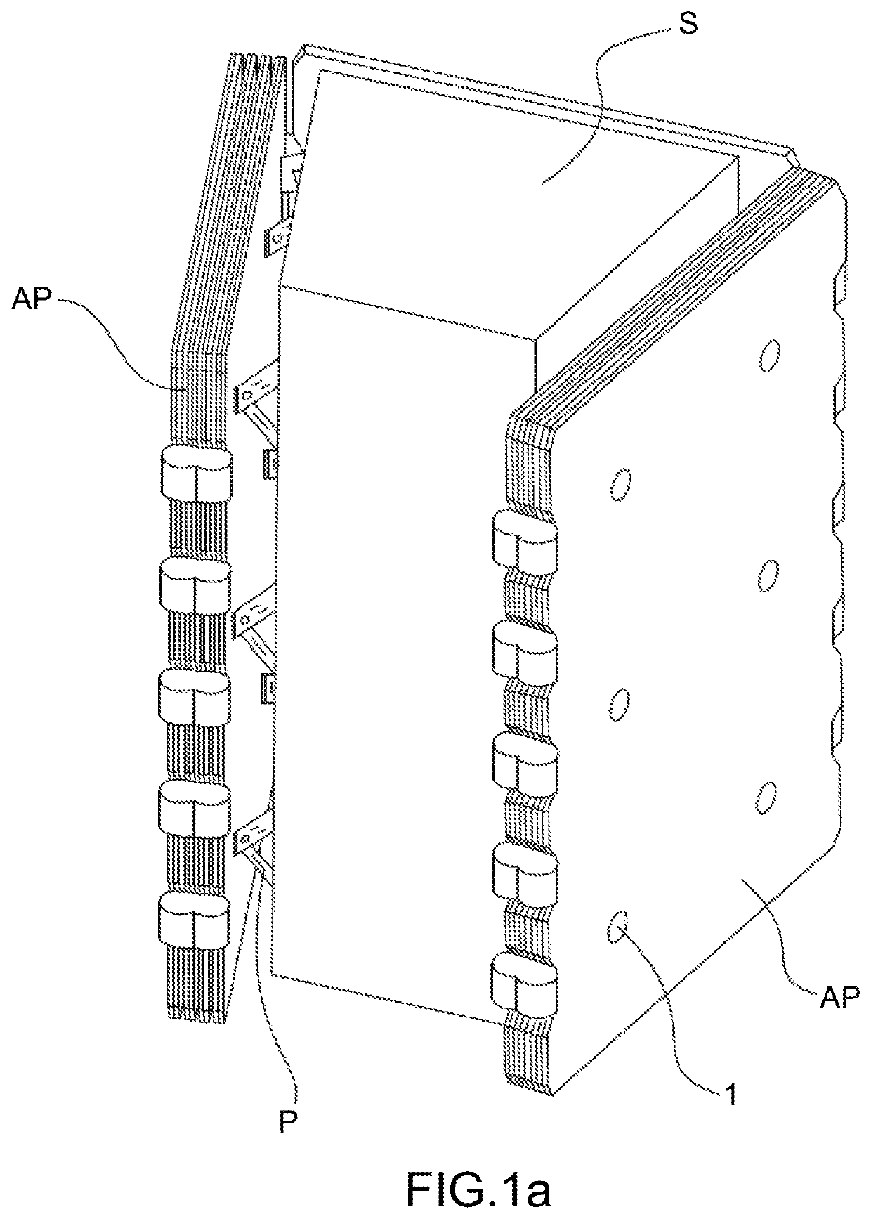
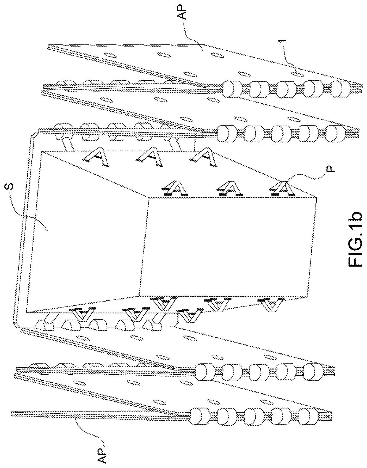
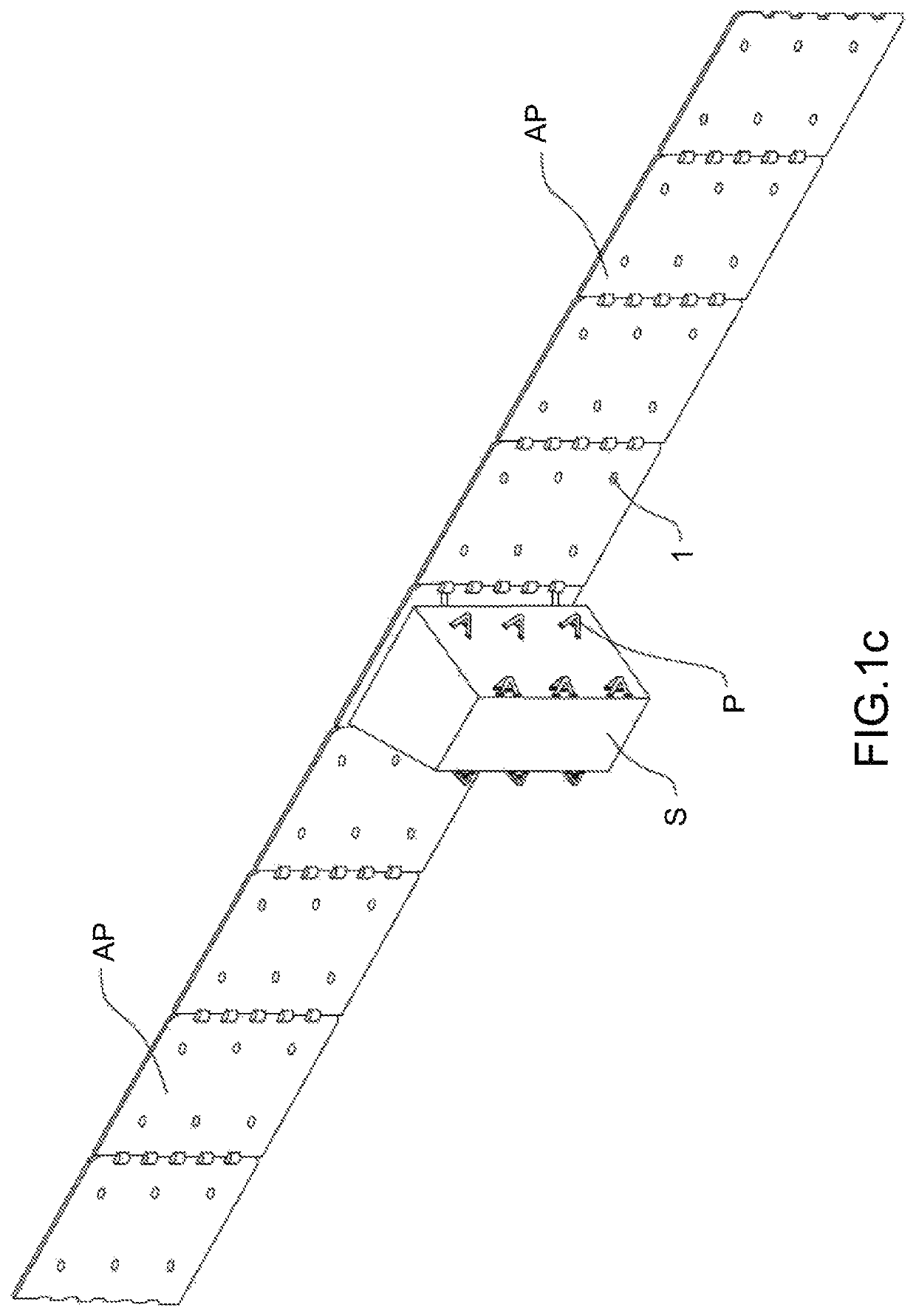
[0039]The objective of FIGS. 1a, 1b, 1c is to show in a very simple manner an example of a satellite having deployable spacecraft appendages. In these three figures there is represented a satellite consisting of a body S with spacecraft appendages AP such as solar generators on respective opposite sides of the body S. In FIG. 1a, the spacecraft appendages AP are in the stowed position. Here each of the spacecraft appendages AP consists of four panels folded against one another and held in place by an appropriate device. Here that appropriate device includes tripods P on which the folded spacecraft appendages AP rest, each tripod P cooperating with a device that is not shown consisting ...


PUM


Abstract

An active tie rod for retaining and releasing appendages without shock is provided. The device comprises: a fixed base, a tie rod extending along an axis between two ends, a mechanism fastened to the base and temporarily retaining a first end of the tie rod, operating the mechanism to release the tie rod from the base, an end piece fastened to a second end of the tie rod, at least one appendage temporarily retained between the base and the end piece, a component disposed between the mechanism and the end piece, and an actuator of the component to modify a characteristic dimension of the component along the axis between two values, the component producing a tension in the tie rod for the first of the two values and the tension in the tie rod being reduced for a second of the two values.

Description

CROSS-REFERENCE TO RELATED APPLICATIONS[0001]This application claims priority to foreign French patent application No. FR 1502636, filed on Dec. 18, 2015, the disclosure of which is incorporated by reference in its entirety.FIELD OF THE INVENTION[0002]The present invention is particularly but not exclusively concerned with the aerospace field and to be more precise consists in an active tie rod for retaining and releasing appendages without shock, for example spacecraft appendages.[0003]By spacecraft appendages is meant equipment intended to be deployed in space, such as solar generators or antennas for example. The invention consists in a simple and robust solution making it possible to release such appendages without shock.BACKGROUND[0004]An active tie rod has initially the function of retaining in a stowed configuration one or more spacecraft appendages, i.e., generally speaking, mobile elements deployable on either side of the body of the satellite, and after that releasing thos...

Claims


Application Information

Patent Timeline
Patent Type & Authority Patents(United States)
IPC IPC(8): B64G1/22B64G1/10B64G1/44
CPCB64G1/443B64G1/222B64G1/10
Inventor BLANC, ALAIN-VINCENTCOMBERNOUX, THOMASMICHELLET, FRANÇOISCHASSOULIER, DAMIEN
Owner THALES SA
Why Eureka
Eureka Blog
Learn More