System and method for removing seam artifacts

a technology of artifact removal and seam artifact, applied in the field ofgraphics processing, can solve the problems of breaking affecting the visual continuity of the image, and the model would be very complex and time-consuming to process and display, so as to reduce the amount of artifacts and reduce the effect of seam artifacts

Active Publication Date: 2009-09-03
AUTODESK INC
View PDF10 Cites 17 Cited by
  • Summary
  • Abstract
  • Description
  • Claims
  • Application Information

AI Technical Summary

Benefits of technology

[0011]During rendering, shader programs executing in a graphics rendering pipeline may be configured to fetch samples from both the initial UV set and the second UV set, weight these samples by the distance from the seams, and blend and interpolate the samples to minimize any artifacts. For example, the second UV set may be ...

Problems solved by technology

Although such details may be modeled as values attached to the vertices of geometries in a 3D model of a given object, such a model would be very complex and time-consuming to process and display.
Unfortunately, when the object is rendered for display purposes and the UV set is applied to the surface of the 3D model, artifacts are often visually apparent along the seams where the edges of the UV pieces abut.
These seam artifacts break the visual continuity of the image and d...

Method used


Image

  • System and method for removing seam artifacts
  • System and method for removing seam artifacts
  • System and method for removing seam artifacts

Examples


Embodiment Construction

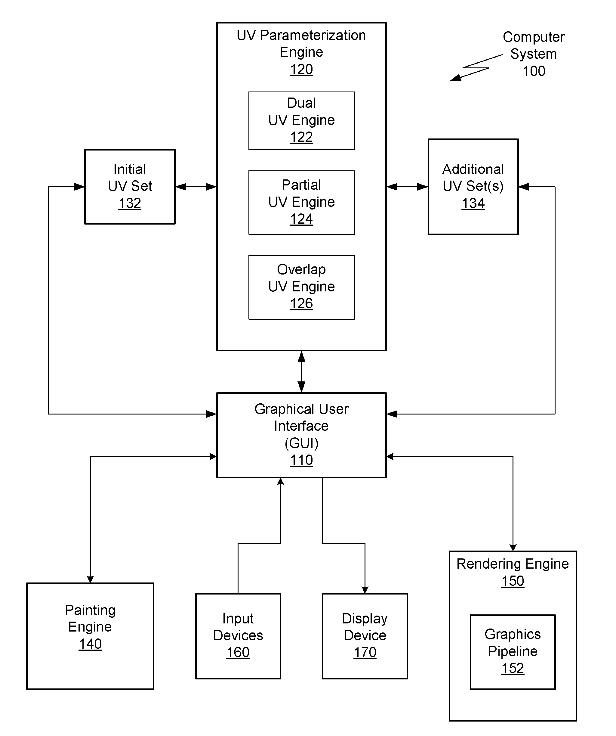
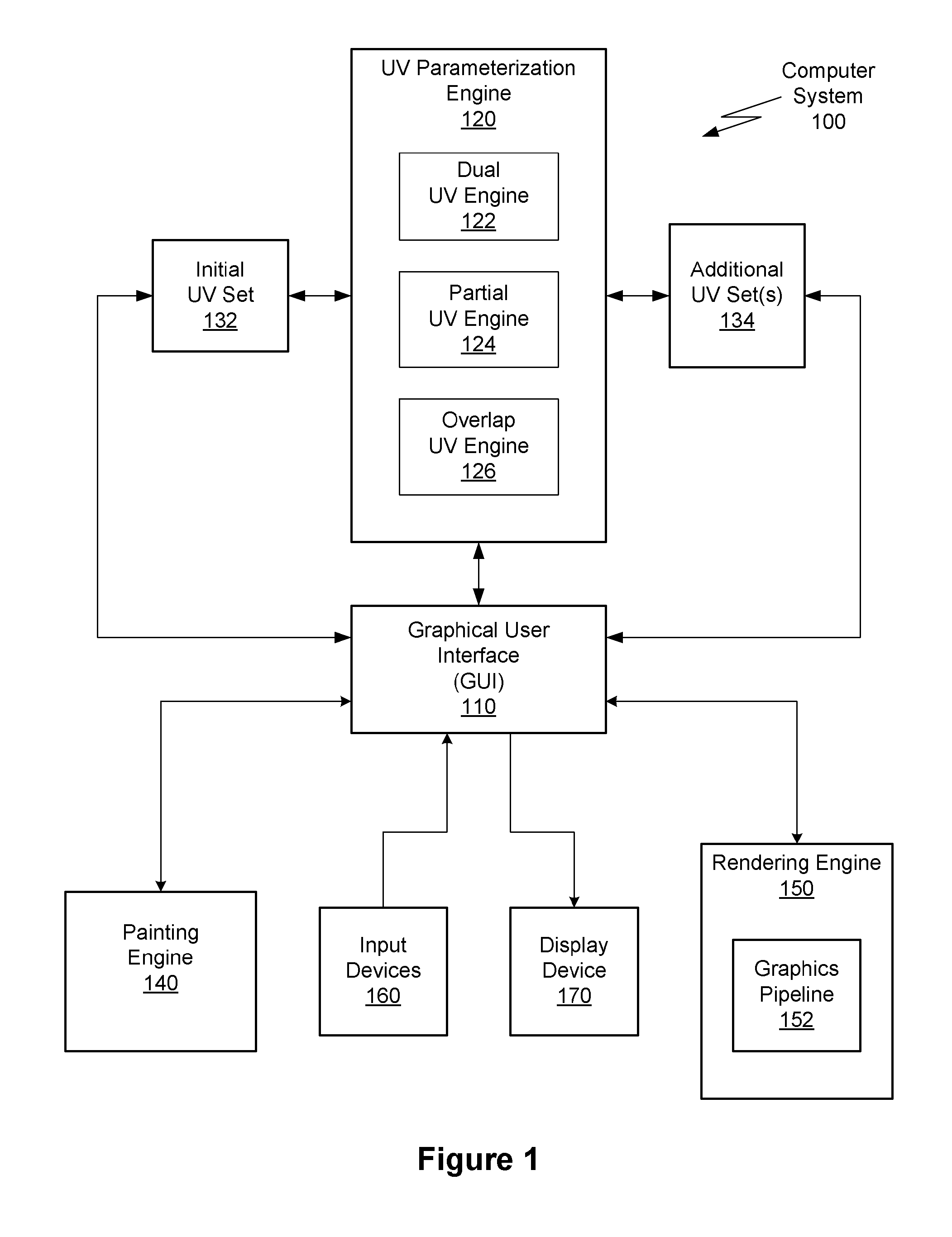
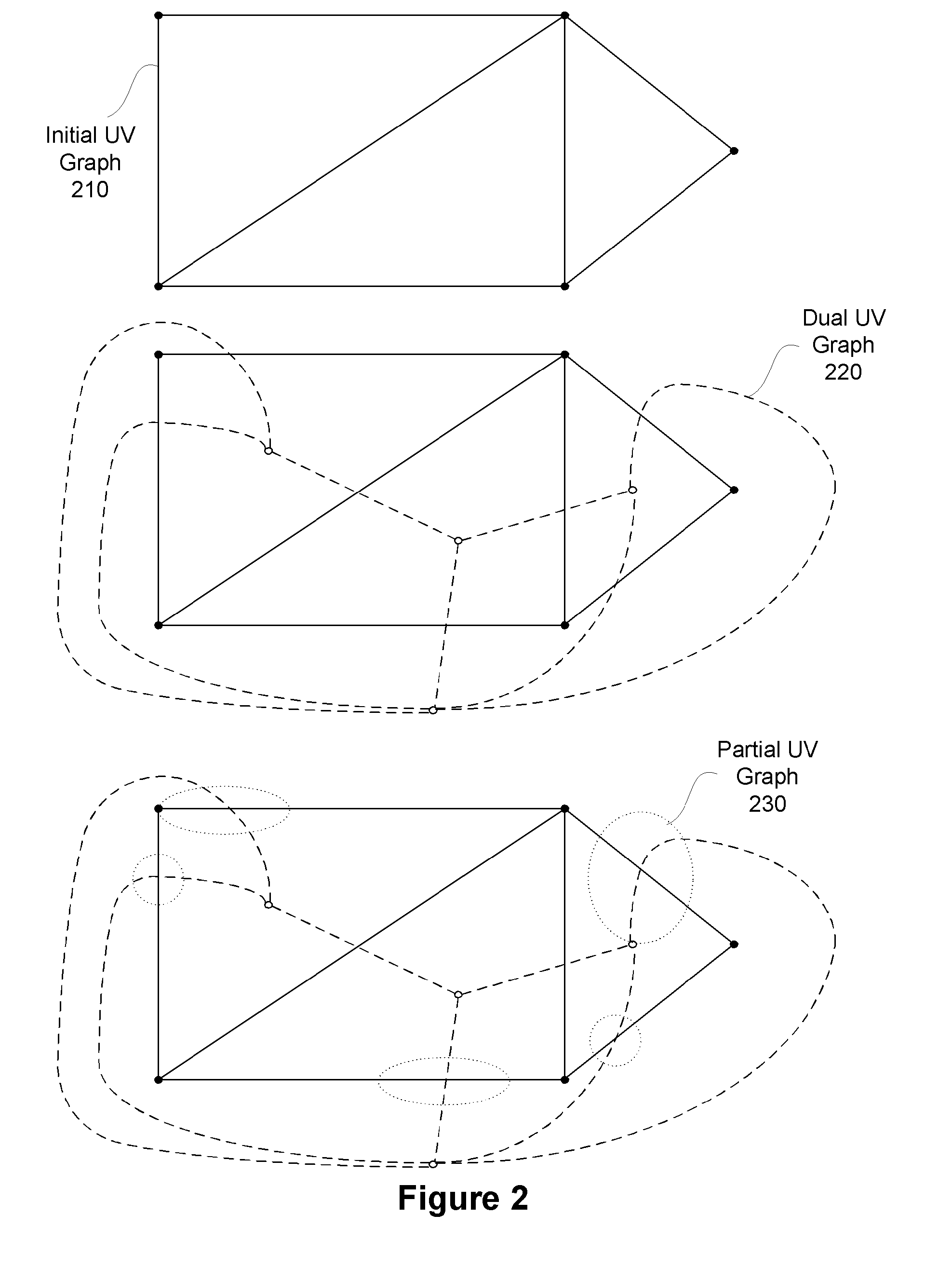
[0021]Embodiments of the invention provide a rendering technique where multiple overlapping UV sets are used to improve the visual quality of a texture rendered on a surface. In one embodiment, one or more UV sets are automatically computed from a first UV set, where the seams of the first UV set fall within the interior of a least one of the UV pieces included in the generated UV sets. That is, the seams of the UV sets do not overlap with one another, although the seams may intersect at single points. For example, the second UV set may be computed from a dual graph representation generated from the first UV set. In an alternative embodiment, UV pieces in the first UV set may be augmented by “growing” UV regions from the “corners” of the seams of the first UV set.

[0022]During a painting process used to generate a texture map, for each triangle (or pixel), it may be determined which UV piece(s) within the UV set(s) contribute to painting that triangle (or pixel). Furthermore, each co...


PUM


Abstract

Embodiments of the present invention include techniques for reducing artifacts in rendered images. In one embodiment, a dual UV engine generates a dual of the graph defined by an initial UV set associated with a 3D model. The dual UV engine then uses existing flattening and layout engines to generate a dual UV set from this dual graph. Using the dual graph to define the dual UV set ensures that the seams corresponding to the initial UV set and the dual UV set minimally intersect.

Description

BACKGROUND OF THE INVENTION[0001]1. Field of the Invention[0002]The present invention generally relates to graphics processing, and more specifically, to a system and method for removing seam artifacts when rendering a graphics image depicting a three-dimensional (3D) object using component pieces of a two-dimensional (2D) UV parameterization of a texture map.[0003]2. Description of the Related Art[0004]A broad variety of computer-based applications support graphical 3D models of real or imaginary objects. For example, computer aided design (CAD) applications are commonly used to compose 3D models representing real-world constructs that are related to construction projects, such as a house or a terrain surface. Similarly, computer game applications may use 3D models of imaginary constructs, such as fictitious characters, to allow users to visually interact with the constructs in a realistic fashion. Once composed, 3D models are often used to generate two-dimensional (2D) images for ...

Claims


Application Information

Patent Timeline
IPC IPC(8): G06T15/00G06T15/04
CPCG06T15/04
Inventor MAILLOT, JEROME
Owner AUTODESK INC
Why Eureka
Try Eureka