
Gravity measurement methods for monitoring reservoirs

a gravity measurement and reservoir technology, applied in the field of gravity measurement, can solve the problems of high computational cost of optimization and solve the problem of high computational cost, and achieve the effects of low computational cost, fast response, and improved accuracy

Active Publication Date: 2009-09-10
SCHLUMBERGER TECH CORP +1
View PDF12 Cites 22 Cited by
  • Summary
  • Abstract
  • Description
  • Claims
  • Application Information

AI Technical Summary

Benefits of technology

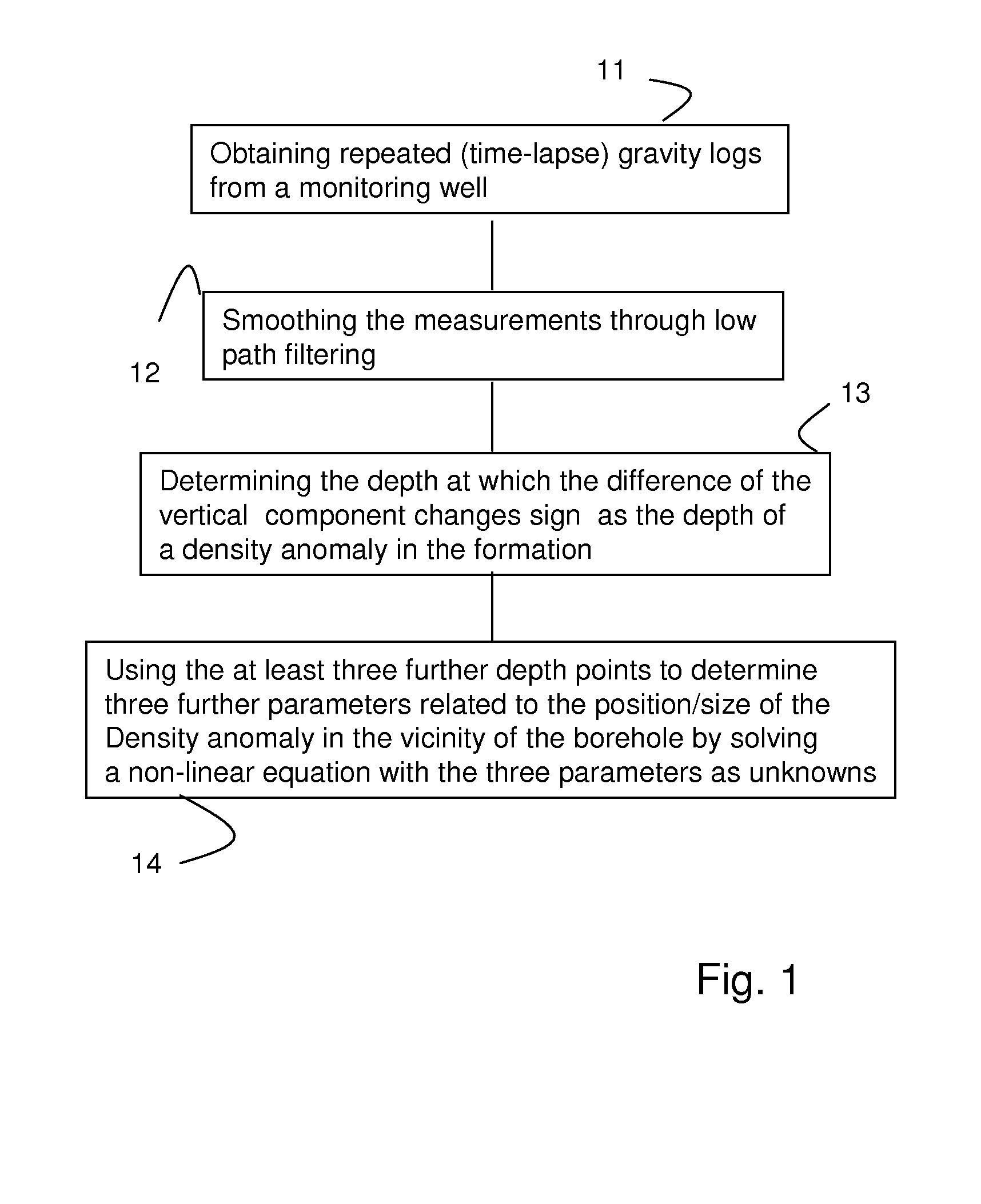
[0016]Given a sufficient number of independent measuring points, which number is larger than the number of unknowns, well-established methods can be used to solve this equation in three unknowns. The method can thus be used to provide at low computational costs estimates of, for example, the location at different times t1 and t2 and the vertical thickness of an arriving fluid front. Used in isolation, the method provides a fast response and requires only time-lapse gravity readings at three depths in the borehole. In cases of a more complex geometry, the method can still make a valuable contribution by providing either a priori information, a first estimate, or constraints to other inversion methods which invert gravity surveys into density anomalies, for example in conventional time-lapse or 4-D reservoir surveys.

Problems solved by technology

In addition, the inverse gravity problem is stated to be fundamentally unstable and it is known that any solution based on an optimization approach involves high computational costs.

Method used


Image

  • Gravity measurement methods for monitoring reservoirs
  • Gravity measurement methods for monitoring reservoirs
  • Gravity measurement methods for monitoring reservoirs

Examples


Embodiment Construction

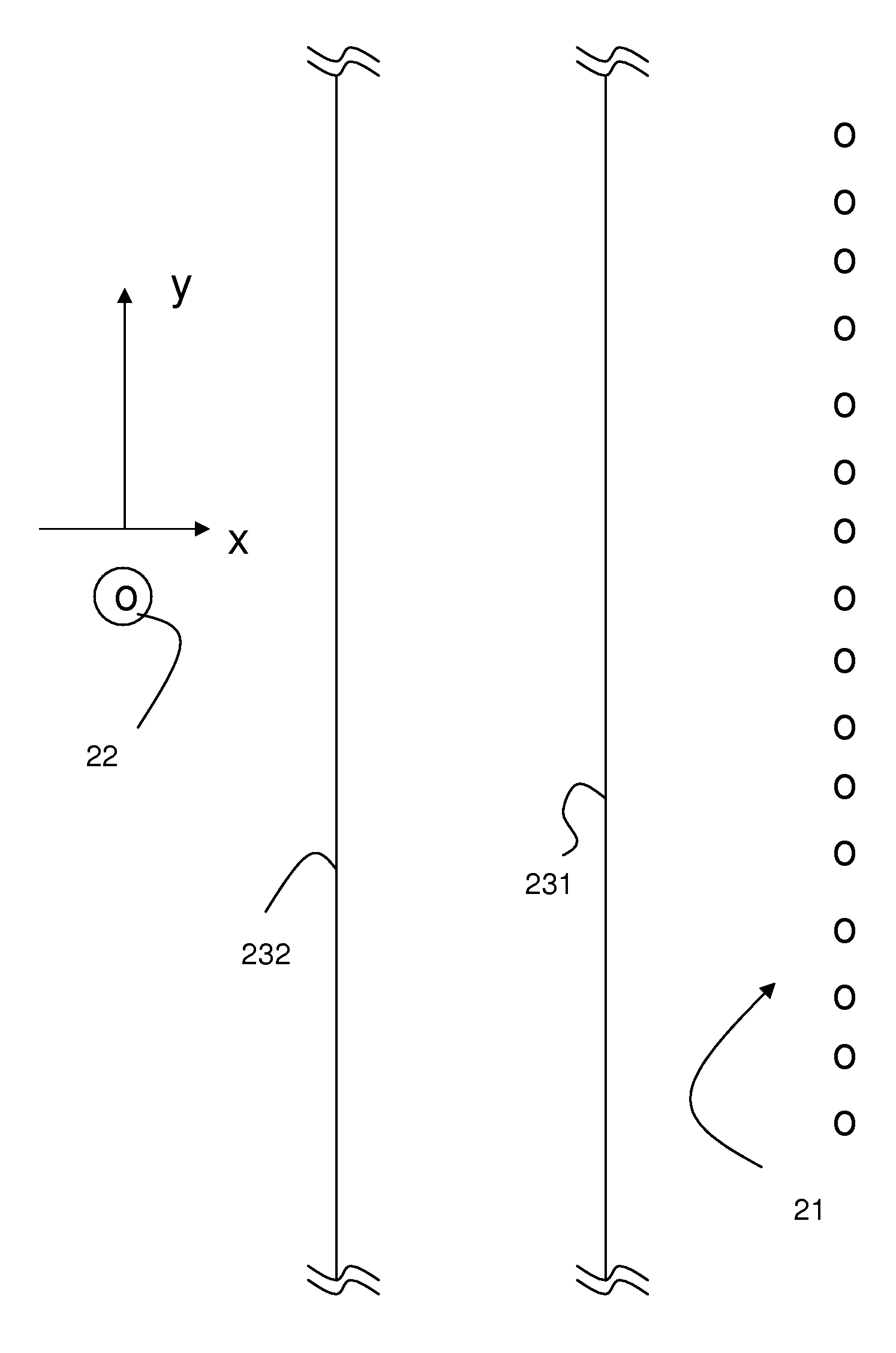
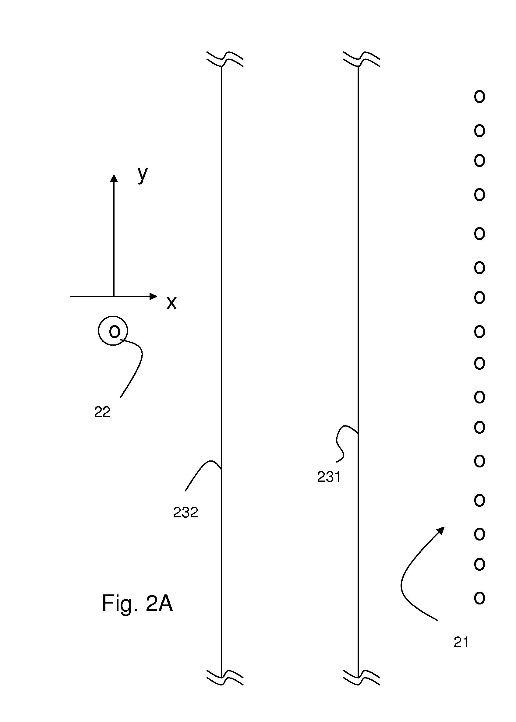
[0022]The following example of a method in accordance with the present invention establishes an analytic relation between the difference of vertical component Δgz of the acceleration due to gravity at an (arbitrary) depth zo at two different times in a borehole due to a semi-infinite horizontal slab with constant density anomaly Δρ.

Δgzslab(z0;xmin,xmax,h)=G·Δρ[xmax·ln(xmax2+(h-z0)2xmax2+(h+z0)2)+xmin·ln(xmin2+(h+z0)2xmin2+(h-z0)2)+2(h-z0)·{tan-1(xmaxh-z0)-tan-1(xminh-z0)}+2(h+z0)·{tan-1(xminh+z0)-tan-1(xmaxh+z0)}][1]

[0023]The variables xmin and xmax denote the algebraic distance (meaning they can take positive or negative values) from the fluid front to a monitoring well where borehole gravity readings have been taken in time-lapse. They correspond to times t2 and t1 respectively. In the example, positive values of xmin (respectively, xmax) refer to cases where the fluid front have not reached the monitoring well at time t2 or t1, respectively, while negative values refer to the opp...


PUM


Abstract

A method of performing gravity surveys in a wellbore is described including performing a time-lapse measurement in a monitoring well in the vicinity of injector wellbores, determining a depth for which the difference of the time lapse measurements changes sign or crosses zero as depth of the anomaly; and using said measurements at other depth points to further determine one or more parameters relating to the location and / or size of a density anomaly caused by injecting fluids through said injector wellbores, thus enabling the sweep of an injected fluid including the occurrence of fingering in the formation.

Description

CROSS-REFERENCE TO RELATED APPLICATIONS[0001]This is a continuation-in-part of Ser. No. 11 / 864,186 filed on Sep. 28, 2007, which is hereby incorporated by reference herein in its entirety.FIELD OF THE INVENTION[0002]The invention relates to the field of gravity measurements to detect changes in a subterranean reservoir.BACKGROUND[0003]Measurements of the earth's gravitational acceleration, and measurements of differences in the earth's gravitational acceleration (gravity difference) between different depths in the earth or horizontal positions, can be useful in determining the bulk density (or specific gravity) of various earth formations, among other applications. More particularly, measurements of gravity difference between two positions or depths may be used to determine whether oil, water or gas primarily fills pore spaces in the earth formations at various depths and geographic locations in the earth.[0004]Such measurements can also be useful in operations where a fluid, such a...

Claims


Application Information

Patent Timeline
IPC IPC(8): G01N9/36E21B47/10E21B45/00E21B44/00G01V7/00
CPCE21B43/16G01V7/00G01N9/36
Inventor DONADILLE, JEAN-MARCALRUWAILI, SALEH B.
Owner SCHLUMBERGER TECH CORP
Learn More