Seat Belt Webbing, Method and Narrow Fabric Needle Loom for Production of Same

a technology of fabric needle loom and seat belt, which is applied in the direction of weaving, textiles, textiles and papermaking, can solve the problems of difficult operation, difficult to master the operation of known devices for producing webbing, and inability to achieve much less than twice the output, etc., to achieve the effect of facilitating the sliding down of weft threads, easy lifting, and soft selvedg

Inactive Publication Date: 2009-09-10
BERGER JOHANN
View PDF41 Cites 10 Cited by
  • Summary
  • Abstract
  • Description
  • Claims
  • Application Information

AI Technical Summary

Benefits of technology

[0035]In another advantageous further embodiment of the method in accordance with the invention multifil threads are employed as weft threads to guarantee a soft selvedge. As a rule multifil threads are also employed as warp threads for seat belt webbing, resulting in the wanted soft selvedge of advantage in the edge portions. In another advantageous further embodiment of the method in accordance with the invention elastic threads are employed. This now makes it possible to produce elastic webbings for ready-to wear garments.
[0036]The object is furthermore achieved by a narrow fabric needle loom as it reads from claim 9 featuring a right-hand weft needle and a left-hand weft needle configured controllably simultaneously to each other, as well as a right-hand and a left-hand weft holdback for retaining and releasing the left-hand and right-hand weft thread respectively, and also being configured to work coordinated to each other, particularly working simultaneously with each other, and a reed. In a further advantageous aspect of the invention the narrow fabric needle loom is characterized in that the weft holdbacks are fixedly secured to the loom and that an elastic arrangement of stripper/holder wires is provided oriented preferably slightly towards the fell suitable for stripping off the weft thread loops before the shed change and before the fell from the weft holdbacks

Problems solved by technology

However, the larger mass and the needed larger and faster movements of the auxiliary pickers resulting from the two weft needles only made it possible to achieve much less than twice the output.
By current standards these known webbings and m

Method used


Image

  • Seat Belt Webbing, Method and Narrow Fabric Needle Loom for Production of Same
  • Seat Belt Webbing, Method and Narrow Fabric Needle Loom for Production of Same
  • Seat Belt Webbing, Method and Narrow Fabric Needle Loom for Production of Same

Examples


Embodiment Construction

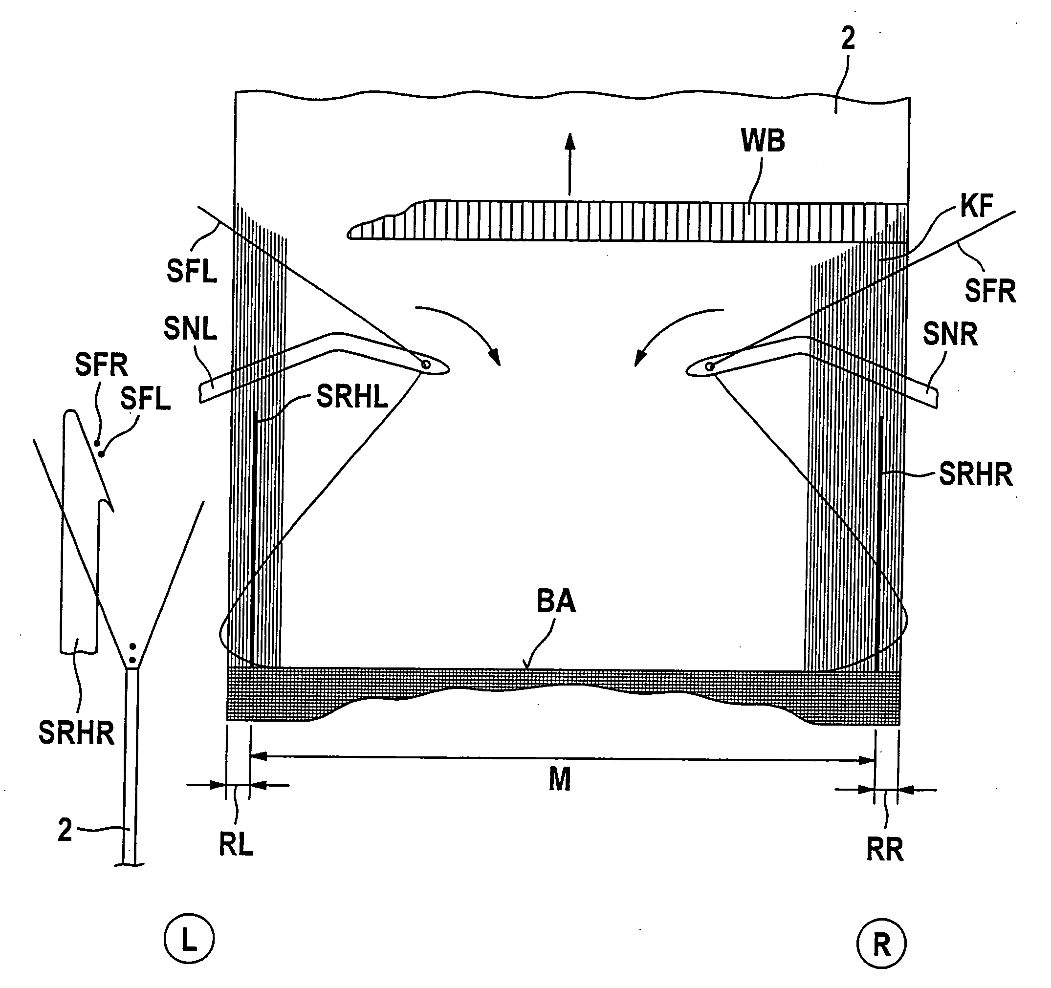
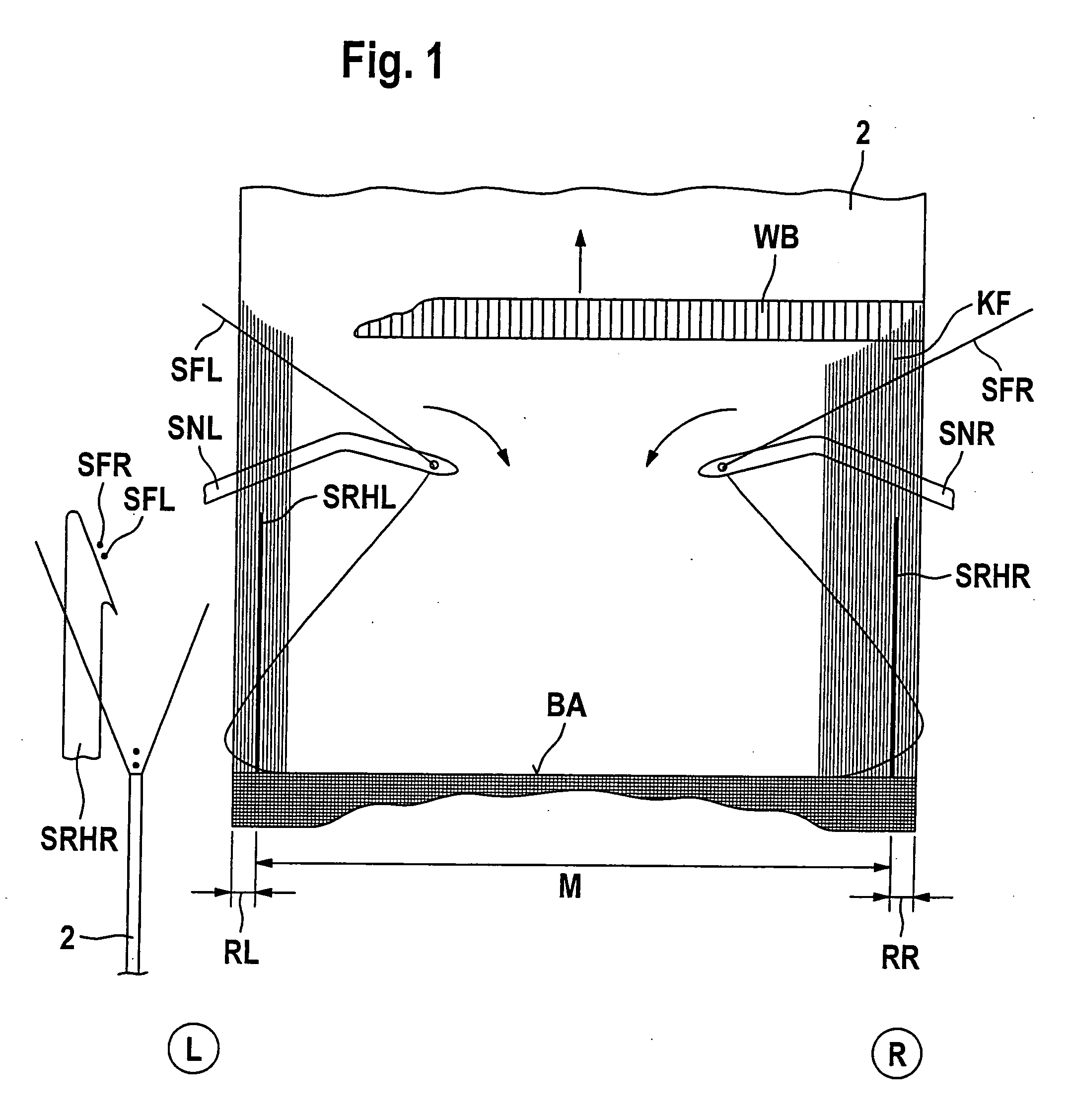
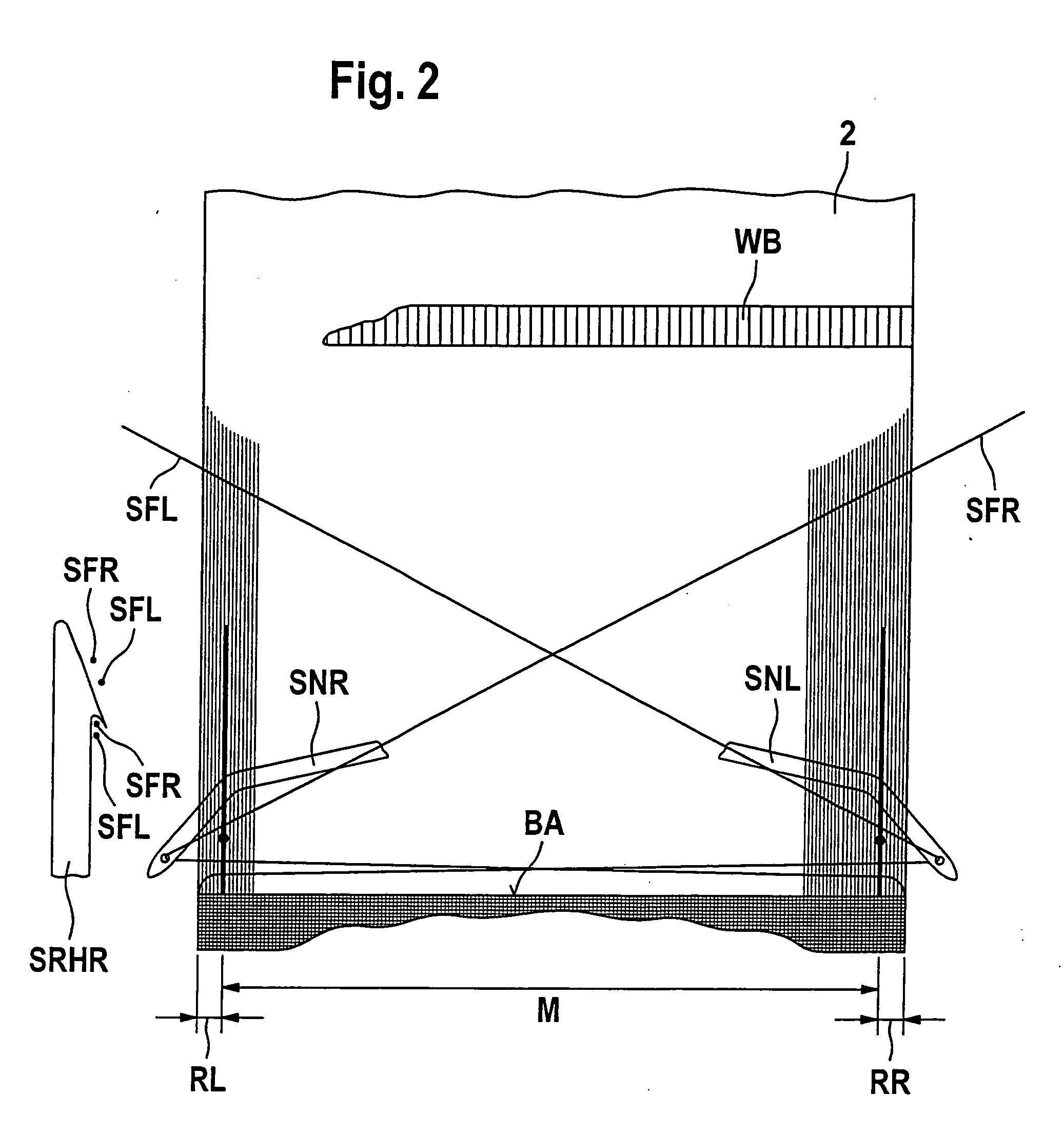
[0055]Referring now to FIG. 1 there is illustrated a seat belt webbing 2 the right and left-hand sides of which correspond to the right and left-hand sides of the drawing in accordance with the capital letters R and L evident encircled below FIG. 1. This applies to all figures as discussed in the following. The seat belt webbing 2 is divided into three portions, a left-hand edge portion RL, an inner portion M and a right-hand edge portion RR. Arranged in each transition portion between the left-hand edge portion RL and inner portion M and between the inner portion M and the right-hand edge portion RR are so-called weft holdbacks SRHR (right-hand) and SRHL (left-hand) evident from FIGS. 2 and 3 by their retaining point symbolized by a thick, black dot. These retaining points are the auxiliary holdback points which by their function lead to each weft reversal points opposite the weft picking side which are located within the material of the seat belt webbing in accordance with the inv...


PUM

PropertyMeasurementUnit
Timeaaaaaaaaaa
Elasticityaaaaaaaaaa

Abstract

The invention relates to a method for weaving a webbing, comprising at least one first (right-hand) weft thread and at least one second (left-hand) weft thread, characterized in that the two weft threads are introduced into the same shed from both sides of the webbing, are wound around weft thread retainers in weft change loops, are substantially retained by the weft thread retainers until shed change and are then stripped off from the left thread retainers by the reed and after shed change and are bound against the stop.

Description

CROSS-REFERENCE TO RELATED APPLICATIONS[0001]This is a National Phase entry of PCT / EP2007 / 002021, filed Mar. 8, 2007, which claims priority to German Application No. 10 2006 010 775.6, filed Mar. 8, 2006, both of which are incorporated by reference herein.BACKGROUND AND SUMMARY[0002]The present invention relates to a method for weaving a webbing comprising a right-hand weft thread (SFR) and a left-hand weft thread (SFL), it also relating to a narrow fabric needle loom.[0003]Known from DE 27 19 382 C3 (Berger) is weaving a single-ply seat belt webbing having tubular selvedges on a narrow fabric needle loom by a sole weft needle. One of two single-ply woven edge portions is pulled up to the selvedge of the middle portion to form the one tubular selvedge by pulling the weft thread.[0004]Known from CH 648 069 A5 (Berger) is a webbing particularly for automotive seat belts made on a narrow fabric needle loom. The webbing features a relatively stiff middle portion and soft edge portions f...

Claims


Application Information

Patent Timeline
IPC IPC(8): D03D41/00D03D23/00
CPCD03D1/0005D10B2401/041D03D47/02D03D13/00D03D35/00D03D15/56D03D15/47D10B2505/122
Inventor BERGER, JOHANN
Owner BERGER JOHANN
Why Eureka
Try Eureka