
Interlocking container

Inactive Publication Date: 2009-09-10
HANA COBI PLASTIC
View PDF4 Cites 17 Cited by
  • Summary
  • Abstract
  • Description
  • Claims
  • Application Information

AI Technical Summary

Benefits of technology

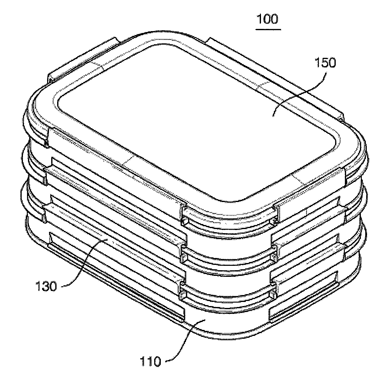
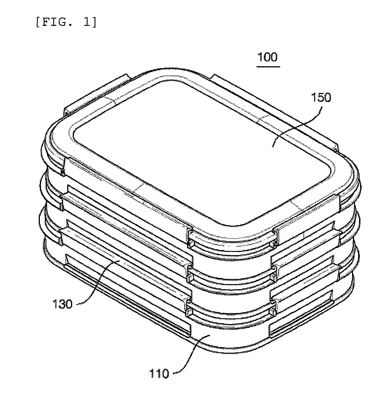
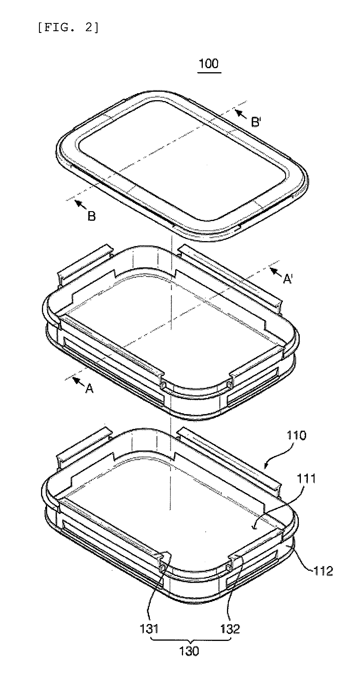
[0007]The present invention is contrived to solve the above-mentioned problems. An object of the present invention is to provide an interlocking container that has grooves grooved at a projecting portion in a predetermined depth through the projecting portion formed on the exterior wall of a container body and a hill portion for closing a part of each of the grooves in the container body and fixation projecting pieces that are inserted into the grooves and are suspended by the hill portion to prevent food from being leaked in a wing.
[0008]Further, another object of the present invention is to provide an interlocking container that considers the aesthetics by disposing a packing in the projecting portion of the container body and the grooves formed on the exterior wall of the container body.
[0017]The present invention takes the following effects in accordance with the above-mentioned configuration. First, it is possible to remarkably improve a fastening force between containers interlocked through grooves formed in a container body and a fixation projecting pieces formed in a wing. It is possible to increase a lifespan of the interlocking container by preventing movement of the interlocking container and preventing a wearing phenomenon generated due to fiction between the containers through inserting a packing into a gap between the exterior wall and the projecting portion.

Problems solved by technology

However, since the coupling holes of the locking wings are not completely coupled with the suspension projections of the container body, fastening force between the containers is loose, which results in the stored contents frequently being discharged to the outside in the known container.
In addition, it is very difficult to form the known container in multiple layers.
However, in the case when several containers are used, several containers occupy too much space inside of a refrigerator.
However, the known container does not have such a structure.

Method used


Image

  • Interlocking container
  • Interlocking container
  • Interlocking container

Examples


Embodiment Construction

[0025]Hereinafter, preferred embodiments of the present invention will be described in detail with reference to the accompanying drawings. First of all, we should note that in giving reference numerals to elements of each drawing, like reference numerals refer to like elements even though like elements are shown in different drawings. Further, in describing the present invention, well-known functions or constructions will not be described in detail since they may unnecessarily obscure the understanding of the present invention. Hereinafter, the preferred embodiment of the present invention will be described, but it will be understood to those skilled in the art that the spirit and scope of the present invention are not limited thereto and various modifications and changes can be made.

[0026]FIG. 1 is a perspective view of an interlocking container according to an embodiment of the present invention. FIG. 2 is an exploded perspective view of an interlocking container according to an e...


PUM


Abstract

The present invention relates to an interlocking container that has a wing provided on the exterior wall of a container body containing contents and fixes the other container body interlocked above the container body by means of the wing. The interlocking container includes a container body that includes a projecting portion bent downward, which is provided at the circumference of an exterior wall, a first groove grooved at an upper end of the projecting portion in a predetermined depth, and a hill portion that is provided at an entrance of the first groove and projects from an upper end of the projecting portion; a wing that includes a pair of hinges projecting at one side of the exterior wall, a support body hinge-coupled with the hinge, and a fixation projecting piece projecting on one end of the support body to form a predetermined angle to the support body, which fits in the first groove through the fixation projecting piece; and a cover that includes the projecting portion provided at the circumference of the exterior wall and the hill portion provided on the top surface of the projecting portion, which covers the upper part of the container body. According to the present invention, fastening force between interlocked containers is improved, contents stored in the container are prevented from being leaked to the outside, and a lifespan is also increased.

Description

BACKGROUND OF THE INVENTION[0001]1. Technical Field[0002]The present invention relates to an interlocking container. More particularly, the present invention relates to an interlocking container that has a wing provided on the exterior wall of a container body containing contents and fixes the other container body interlocked above the container body by means of the wing.[0003]2. Related Art[0004]In general, a container body containing food is molded by synthetic resin, heat-resistant glass, heat-resistant ceramics, etc. which are materials permitted for food storage. Among them, the product molded by the synthetic resin can be mass-produced, is low-priced, and is convenient to handle, as a result the product molded by the synthetic resin is most widely used. Locking devices are provided in a main body and a cover of the container in order to safely keep and store food stored in an airtight container and prevent the food from being leaked.[0005]A plurality of suspension projections ...

Claims


Application Information

Patent Timeline
IPC IPC(8): B65D21/00
CPCB65D45/22B65D21/0213B65D21/02B65D43/02B65D1/22
Inventor KIM, CHANG HO
Owner HANA COBI PLASTIC
Learn More