Apparatus for cleaning stationary, permanent vertical cylindrical cartridges incorporating a float affixed to a central and linearly traversable backwash tube incorporating spray nozzles to induce rotation

a backwashing apparatus and stationary technology, applied in the direction of sedimentation settling tanks, separation processes, filtration separation, etc., can solve the problems of inability to remove all existing contaminants, time-consuming and expensive tasks, and the inability to clean these filters manually, so as to reduce the nozzle and backwash flow, reduce the waste of processed water, and improve the use of long tube area filters

Inactive Publication Date: 2009-09-10
HIRS GENE
View PDF10 Cites 3 Cited by
  • Summary
  • Abstract
  • Description
  • Claims
  • Application Information

AI Technical Summary

Benefits of technology

[0006]In this fashion, a 90% reduction in the nozzle and backwash flow can be achieved in comparison to that needed in the event of employing stationary fluid jets. Specifically, and again in the example of filtration vessel with 6′ backwash tube, an embodiment of the present invention is capable of incorporating eight combination rotating and linearly traversing nozzles, thus using a total volume of 16 gallons per minute (GPM) of water. In comparison, a total of 78 stationary nozzles expending 156 GPM would be required in providing the same backwash effect. As such, the present invention results in better use of long tube area filters, with lesser wasted processed water and more efficient cleaning processes.

Problems solved by technology

Settling tanks and pre-filtration often do not remove all existing contaminants which have accumulated during normal fluid flow.
Cleaning of these filters require manual labor, including disassembly and replacement of the cartridge elements.
Such tasks are time consuming and expensive, both in terms of part and labor costs.
This does not work effectively if longer tubes are used, since the liquid does not backwash effectively and most of the backwash simply escapes at the lower end of the element.

Method used


Image

  • Apparatus for cleaning stationary, permanent vertical cylindrical cartridges incorporating a float affixed to a central and linearly traversable backwash tube incorporating spray nozzles to induce rotation
  • Apparatus for cleaning stationary, permanent vertical cylindrical cartridges incorporating a float affixed to a central and linearly traversable backwash tube incorporating spray nozzles to induce rotation
  • Apparatus for cleaning stationary, permanent vertical cylindrical cartridges incorporating a float affixed to a central and linearly traversable backwash tube incorporating spray nozzles to induce rotation

Examples


Embodiment Construction

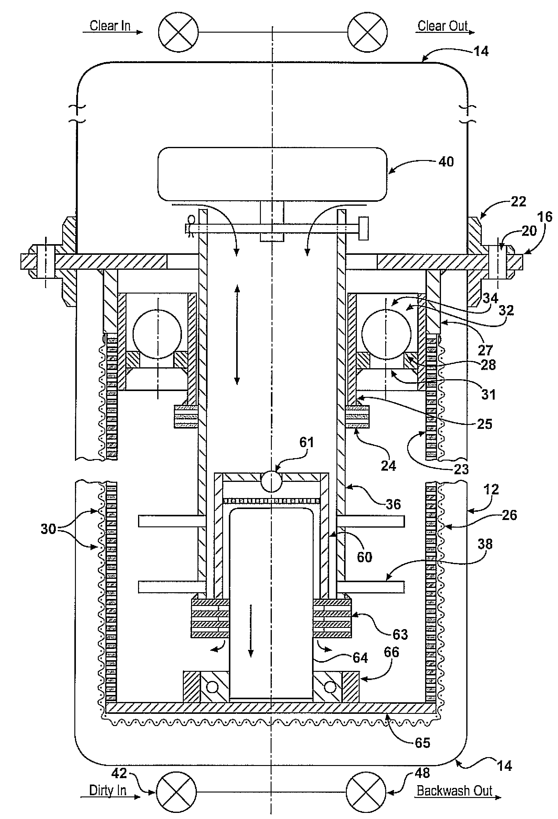
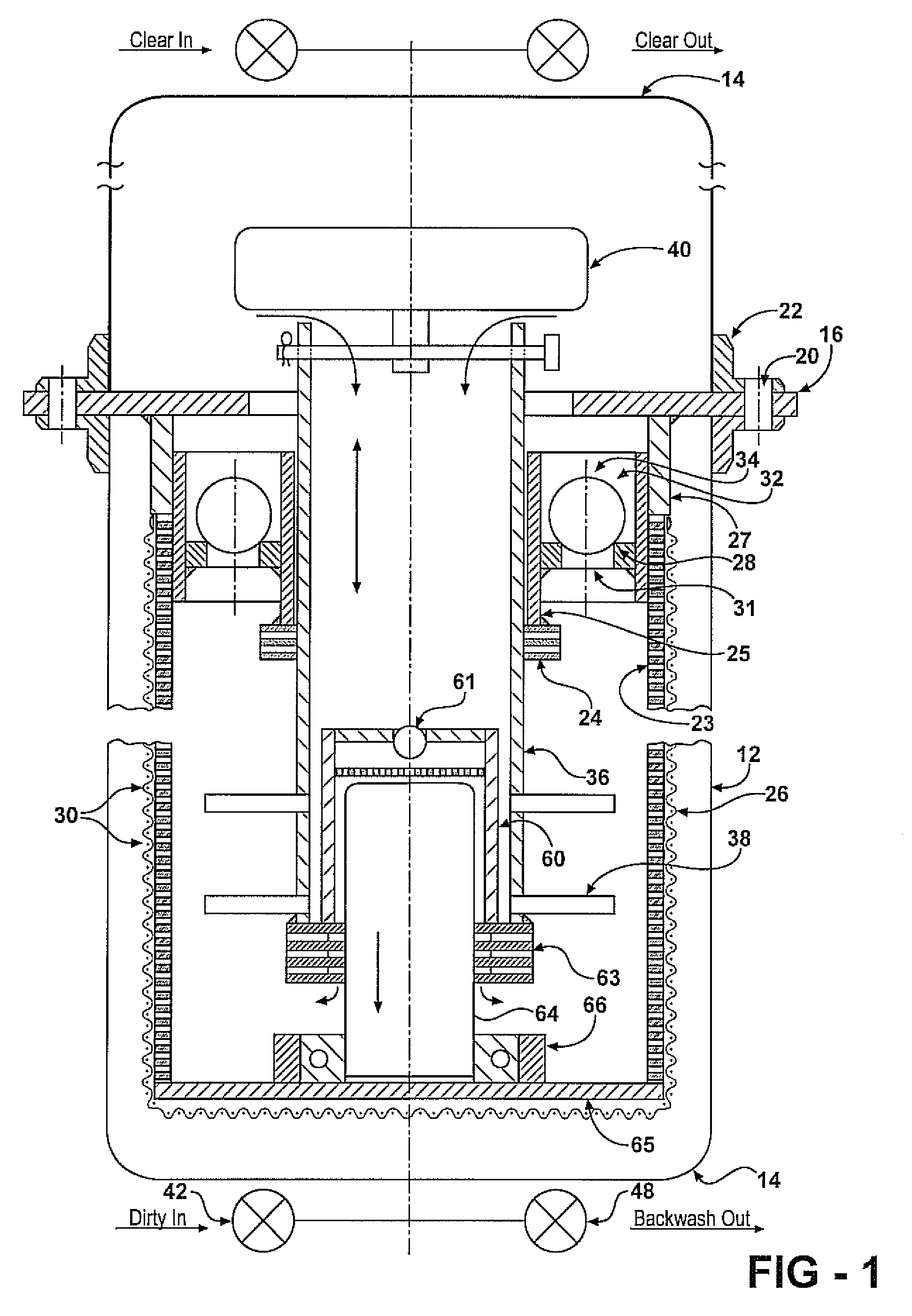
[0010]FIG. 1 is a cross section view of the filter vessel and the internal cartridge.

[0011]The filter vessel consists of a top head dome section 14, and a bottom tube body section 12, with a platen 16, between them and bolted 20, through flanges 22. Vessel has filter valves 42 and 44 and backwash valves 46 and 48, and a base 65.

[0012]The inside of the vessel contains filter cartridges 30, affixed to the platen 16, and disposed vertically. The filtration area consisting of a perforate tube 23, covered with a filter bag 26, made of a polymeric fabric, covering the outside of the perforate tube 23.

[0013]The cartridge 30, contains a central backwash tube 36, which is affixed to a float 40, in the top dome 14, and enters the cartridge 30, and is contained in a guide tube 25, and extending downwardly with a series of spray nozzles 38, mostly directed to the filter septum 26, and partially deflected to create a tangential torque for tube rotation.

[0014]The cartridge 30, near the top also c...


PUM

PropertyMeasurementUnit
lengthaaaaaaaaaa
hydraulic pressureaaaaaaaaaa
flow rateaaaaaaaaaa

Abstract

A liquid filter with multiple vertical filter tubes covered with a permanent filter septum that can be backwashed through an inner backwash tube with radial nozzles that rotate the tube and advances it up by a float in the top clean compartment and descends with liquid pressure.

Description

FIELD OF THE INVENTION[0001]An improved backwash apparatus, such as incorporated into a liquid filtration pressure vessel incorporating a plurality of stationary and permanent cylindrical shaped filter cartridges.BACKGROUND OF THE INVENTION[0002]Pressure liquid filters containing a wire mesh or synthetic bag elements are extensively used as a final polishing filter. Settling tanks and pre-filtration often do not remove all existing contaminants which have accumulated during normal fluid flow. Therefore, and during critical machining operations, an absolute removal of all such contaminants is imperative.[0003]Bag filters and other types of cartridge filters are also often employed. Cleaning of these filters require manual labor, including disassembly and replacement of the cartridge elements. Such tasks are time consuming and expensive, both in terms of part and labor costs.[0004]Other permanent element tube filters backwash with the shock introduction of compressed air. This does no...

Claims


Application Information

Patent Timeline
Patent Type & Authority Applications(United States)
IPC IPC(8): B01D35/22
CPCB01D29/114B01D29/682
Inventor HIRS, GENE
Owner HIRS GENE
Why Eureka
Try Eureka