Brushless motor

a brushless motor and motor shaft technology, applied in the direction of dynamo-electric machines, magnetic circuit rotating parts, magnetic circuit shapes/forms/construction, etc., can solve the problems of cost-performance, the cogging torque cannot be reduced so much, waste of magnet material in any motor using segment magnets, etc., to reduce the number of magnets stacked, the effect of enhancing the output torqu

Inactive Publication Date: 2009-09-10
MITSUBA CORP
View PDF9 Cites 12 Cited by
  • Summary
  • Abstract
  • Description
  • Claims
  • Application Information

AI Technical Summary

Benefits of technology

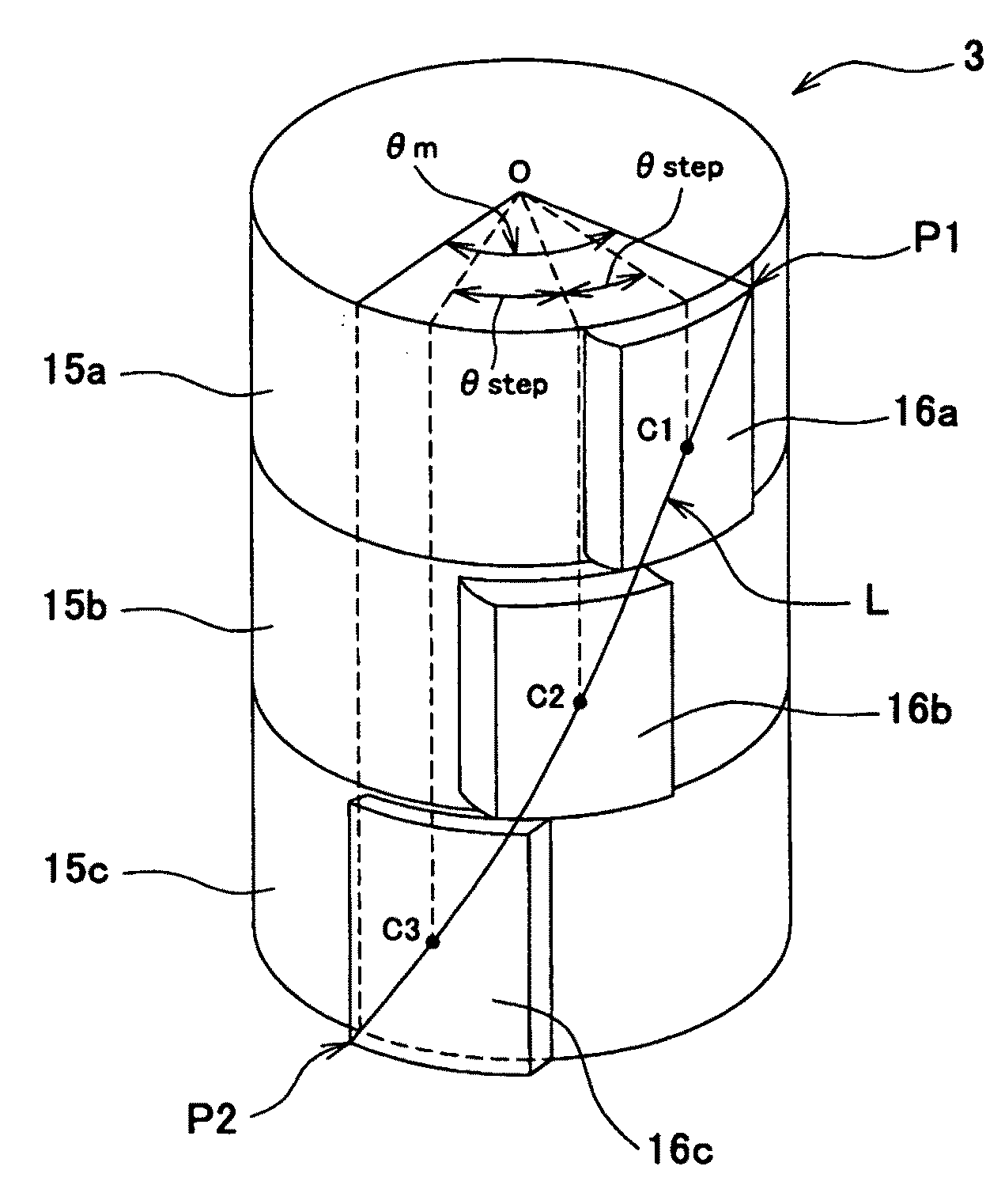
[0012]In the present invention, using a three-stage skew structure in a 2P3S×n structure motor, the line induced voltage can contain the fifth harmonic component, and the waveform of the voltage can be changed to a trapezoidal waveform. This can reduce the cogging torque and enhance the output torque while decreasing the number of magnets stacked to a minimum.
[0013]In the brushless motor, the segment magnets may have a skew angle θskew ranging from 36° to 57° in terms of electrical angle. This renders the fifth harmonic component more prominent in the induced voltage, which contributes to make the waveform of the voltage trapezoidal. Further, in the brushless motor, the ratio ...

Problems solved by technology

Inevitably, the magnet material is wasted in any motor using segment magnets.
Consequently, the motor involve the problem of cost-performance.
Inevitably, the cogging torque cannot be reduced so much in the two-staged, step-skew structure.
However, such a small skew...

Method used


Image

  • Brushless motor
  • Brushless motor
  • Brushless motor

Examples


Embodiment Construction

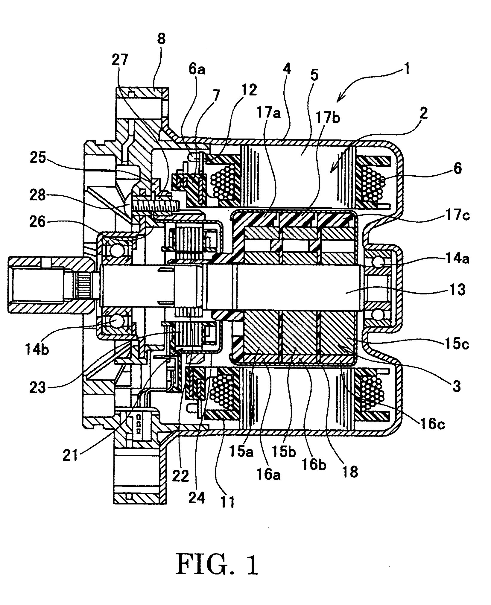
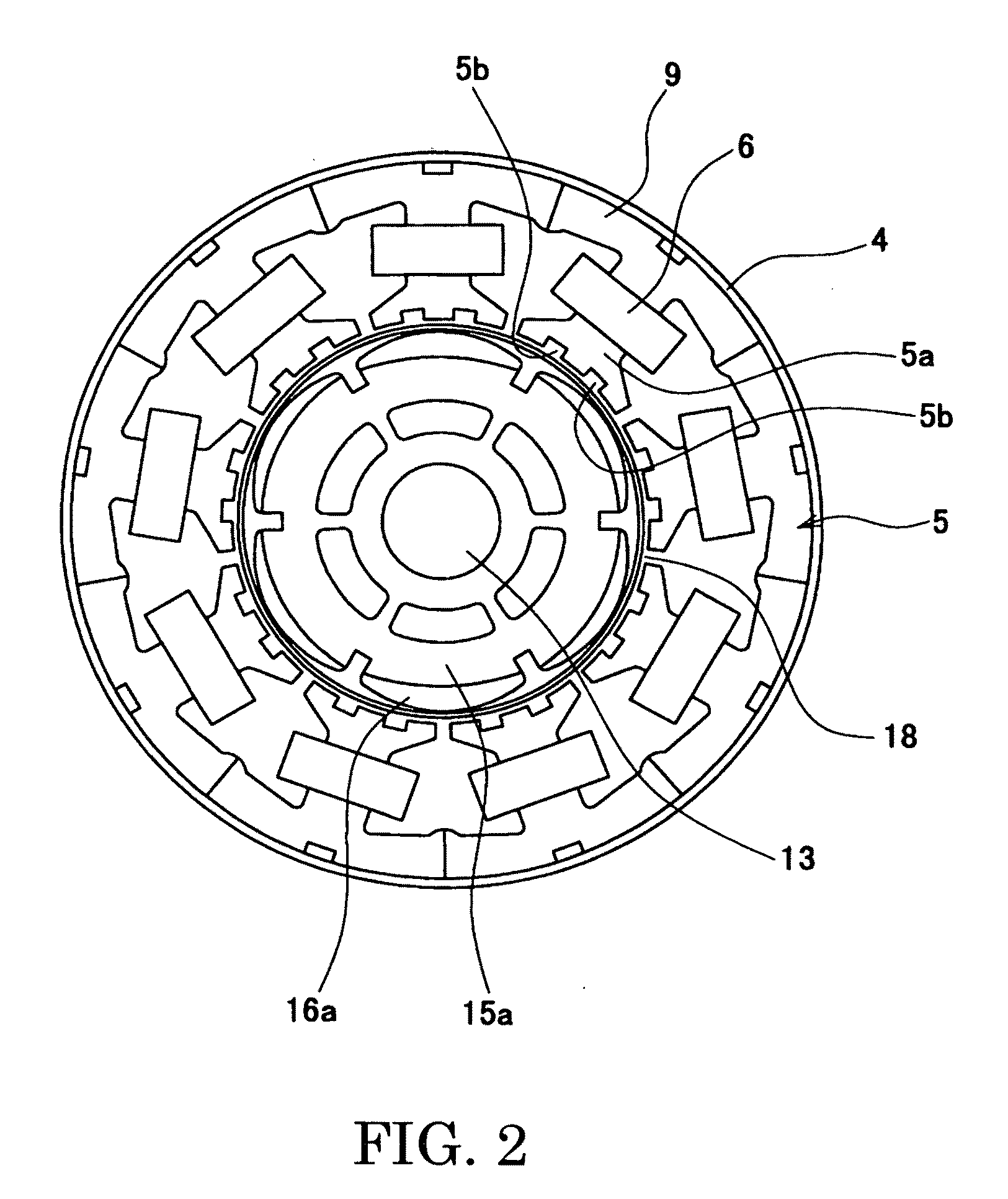
[0025]An embodiment of the present invention will be described in detail, with reference to the accompanying drawings. FIG. 1 is a sectional view of a brushless motor according to an embodiment of the present invention. As shown in FIG. 1, the brushless motor 1 (hereinafter referred to as “motor 1”) is an inner-rotor type that has a stator 2 and a rotor 3 arranged in the stator 2. For example, the motor 1 may be used as the power source of an electric power-steering (EPS) apparatus of column-assist type. The motor 1 can apply an auxiliary drive force to the steering shaft. The motor 1 is secured to a speed-reducing mechanism, which is in turn coupled to the steering shaft. The speed-reducing mechanism reduces the rotational speed of the motor 1 and transmits the rotation to the steering shaft.

[0026]The stator 2 includes a case 4, a stator core 5, stator coils 6, and a bus-bar unit (terminal unit) 7. The stator coils 6 (hereinafter called “coils 6”) are wound around the stator core 5...


PUM


Abstract

In a brushless motor includes a rotor having 2n magnetic poles and a stator having 3n slots, the magnetic poles of the rotor are composed of segment magnets arranged in three columns extending in an axial direction. The magnets of each column are displaced from the magnet of either adjacent column in a circumferential direction, forming a 3-stage step-skew structure. The segment magnets have a skew angle θskew ranging from 36° to 57° in terms of electrical angle.

Description

BACKGROUND OF THE INVENTION[0001]1. Field of the Invention[0002]The present invention relates to a brushless motor that has a skew structure. More particularly, the invention relates to a brushless motor of having a step-skew structure by means of segment magnets.[0003]2. Related Art Statement[0004]Hitherto, harmonic components have been used in brushless motors for use in electric power steering (EPS) apparatuses, changing the waveform of the line induced voltage between any adjacent lines to a trapezoidal waveform to increase the rate of utilization of motor induced voltage so that the motors may be small and generated a large output as demanded. Generally, the voltage induced in a brushless motor can contain a prominent fifth harmonic component and a prominent seventh harmonic component if the motor has an integral multiple of 2 poles and 3 slots (this will be hereinafter called “2P3S×n”). If the induced voltage contains a fifth harmonic component, in particular, it will have a t...

Claims


Application Information

Patent Timeline
IPC IPC(8): H02K1/27
CPCH02K1/278H02K2201/06H02K29/03H02K1/2781
Inventor OKUBO, MASAYUKI
Owner MITSUBA CORP
Why Eureka
Try Eureka