Rotor structure for interior permanent magnet electromotive machine

a permanent magnet electromotive machine and rotor structure technology, applied in the direction of dynamo-electric machines, magnetic circuit rotating parts, magnetic circuit shapes/forms/construction, etc., can solve the problems of increasing the transient force, affecting the electromechanical energy conversion efficiency of the traction motor, and affecting the efficiency of the electromechanical energy conversion

Inactive Publication Date: 2009-09-10
GENERAL ELECTRIC CO
View PDF44 Cites 88 Cited by
  • Summary
  • Abstract
  • Description
  • Claims
  • Application Information

AI Technical Summary

Problems solved by technology

Although these machines have proven through the years to be the workhorses of the industry, they sometimes suffer from various drawbacks.
For example, in the case of traction motors, such motors tend to be relatively heavy, and inefficient in terms of electro-mechanical energy conversion.
Moreover, any incremental weight of the traction motors tends to increase the transient forces on the truck (in a rail vehicle) and the road / track.
The slips rings are subject to electro-mechanical wear and tear and may need burdensome and costly maintenance.

Method used


Image

  • Rotor structure for interior permanent magnet electromotive machine
  • Rotor structure for interior permanent magnet electromotive machine
  • Rotor structure for interior permanent magnet electromotive machine

Examples


Embodiment Construction

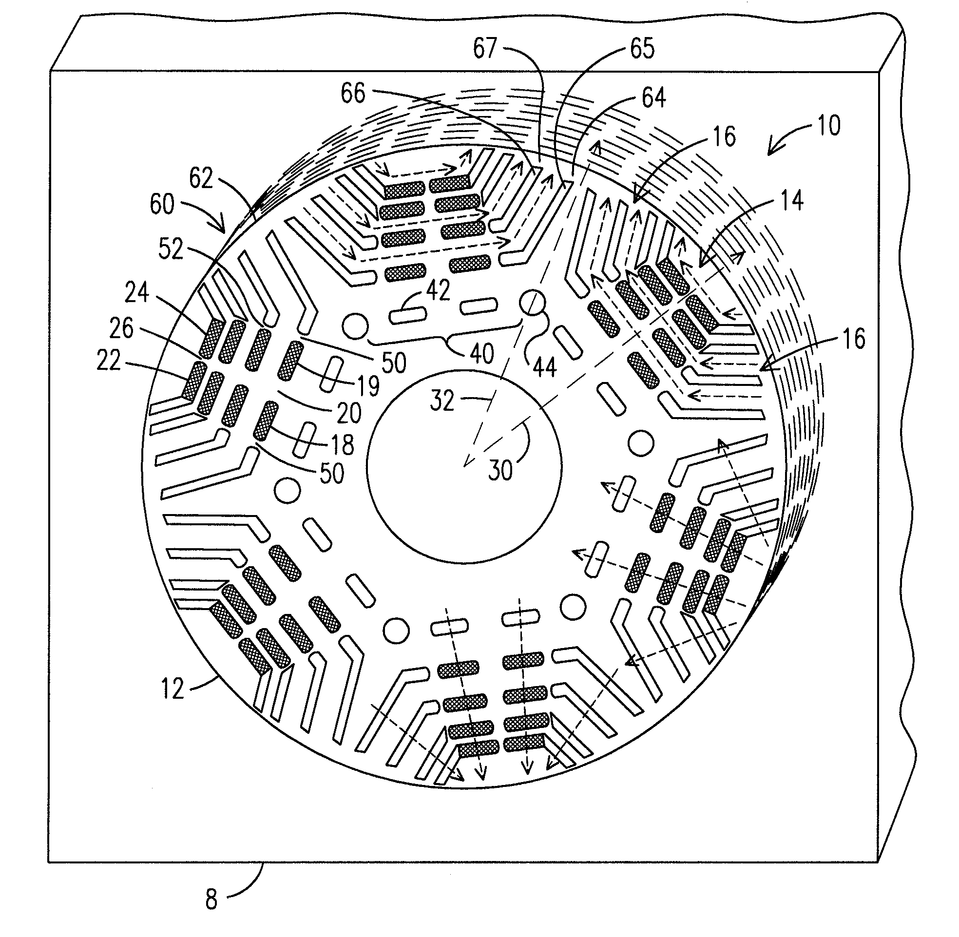
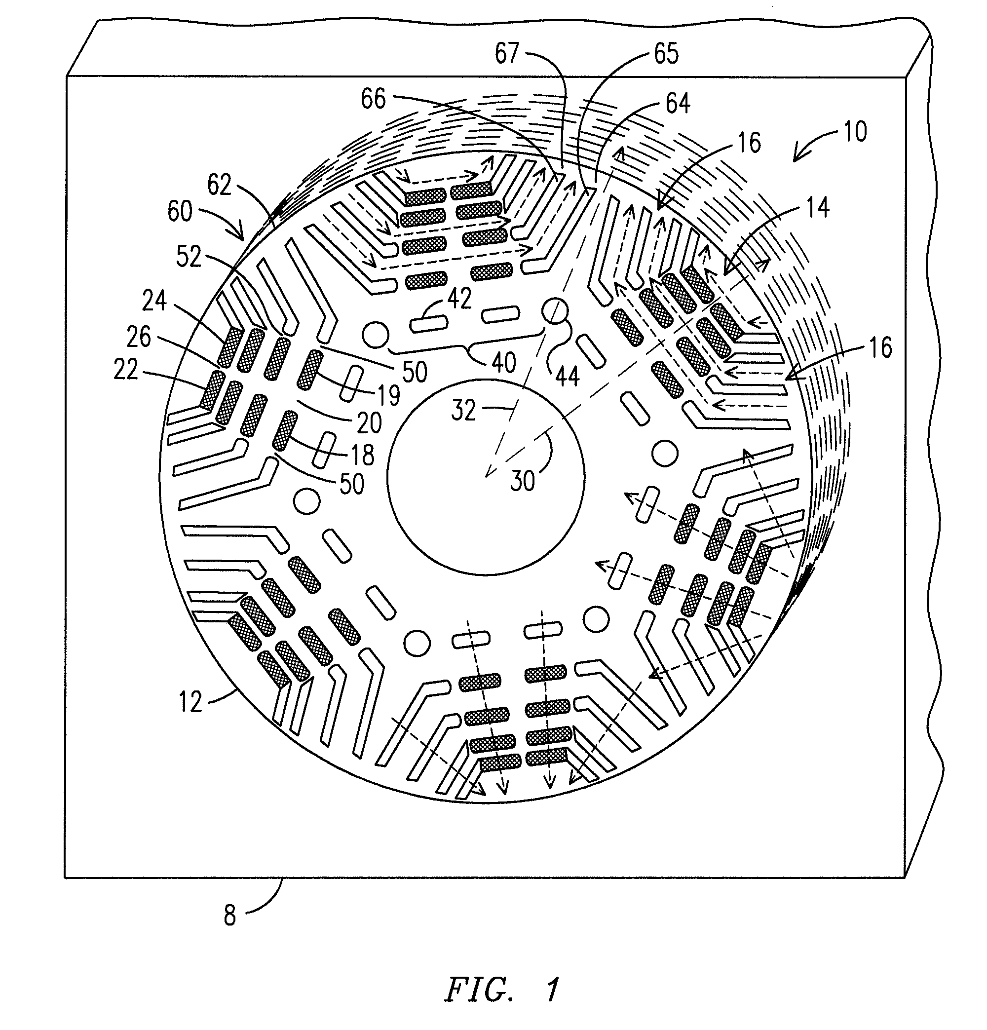
[0009]A hybrid interior permanent magnet (IPM) electromotive machine 8 embodying aspects of the present invention uses an improved rotor structure 10 with enhanced electromagnetic and / or mechanical characteristics. As a result of such enhancements, a rotor structure embodying aspects of the present invention may be advantageously used in relatively large electromotive machines of high power rating in applications that may require operating under a limited input voltage over a broad range of speeds including operation at high speeds, such as typical of locomotives, mining vehicles and other off-highway vehicles (OHV), marine vessels, and stationary applications (e.g., for drilling purposes).

[0010]Rotor structure 10 includes at least one rotor lamination 12 that includes a first group of slots 14 and a second group of slots 16 arranged to form a magnetic pole. (As described in more detail below, “lamination” refers to a thin metal plate or other thin plate, a plurality of which are ty...


PUM


Abstract

A rotor structure for an interior permanent magnet (IPM) electromotive machine is provided. The rotor structure includes at least one rotor lamination including a first group of slots and a second group of slots arranged to form a magnetic pole. The first group of slots may be arranged to form a magnetic flux along a direct axis of the magnetic pole resulting from the first and second group of slots. At least some of the first group of slots is arranged to receive a respective permanent magnet. The second group of slots is arranged to provide a separation for the magnetic flux from adjacent magnetic poles and lying along a quadrature axis of said magnetic pole. At least some of the second group of slots is arranged without a permanent magnet. The rotor structure further includes a magneto-mechanical barrier arranged to reduce a peak level of mechanical stress occurring by the first and/or the second group of slots and/or impede a flow of magnetic flux through the barrier.

Description

[0001]This application claims the benefit of U.S. Provisional Patent Application Ser. No. 61 / 034,348 filed on Mar. 6, 2008, which is incorporated by reference herein in its entirety.FIELD OF THE INVENTION[0002]The present invention is generally related to electromotive machines, and, more particularly, to rotor structures containing buried permanent magnets for relatively large electromotive machines.BACKGROUND OF THE INVENTION[0003]Presently, direct current (DC) or induction electromotive machines are generally used in diesel / electric-based locomotives, in mining vehicles and other off-highway vehicles, in certain marine vessels, and in stationary applications (e.g., for drilling purposes). The machines may be used in various operational contexts, including traction, auxiliary equipment, such as blowers or cooling equipment, and electrical power generating equipment.[0004]Although these machines have proven through the years to be the workhorses of the industry, they sometimes suff...

Claims


Application Information

Patent Timeline
Patent Type & Authority Applications(United States)
IPC IPC(8): H02K1/27
CPCH02K1/276H02K1/246
Inventor KUMAR, AJITH KUTTANNAIRANBARASU, RAMASAMYTRIPATHI, ANSHUMANTIWARI, ARVIND KUMARSCHULTZ, ROY DAVIDJANSEN, PATRICK LEEKALLURI, RAMMOHAN RAOMENON, SHISHIR CHANDRASEKHAR
Owner GENERAL ELECTRIC CO
Why Eureka
Try Eureka