Radio frequency testing system and testing circuit utilized thereby

a radio frequency testing and testing circuit technology, applied in the direction of resistance/reactance/impedence, instruments, transmitter monitoring, etc., can solve the problems of increasing the overall cost of testing, the cost of radio frequency connectors is high, and the industry has not yet addressed the need to overcome the limitations described

Active Publication Date: 2009-09-10
NANNING FUGUI PRECISION IND CO LTD
View PDF3 Cites 5 Cited by
  • Summary
  • Abstract
  • Description
  • Claims
  • Application Information

AI Technical Summary

Problems solved by technology

However, the radio frequency connector is very costly, thereby increasing the overall cost of testing.

Method used


Image

  • Radio frequency testing system and testing circuit utilized thereby
  • Radio frequency testing system and testing circuit utilized thereby
  • Radio frequency testing system and testing circuit utilized thereby

Examples


Embodiment Construction

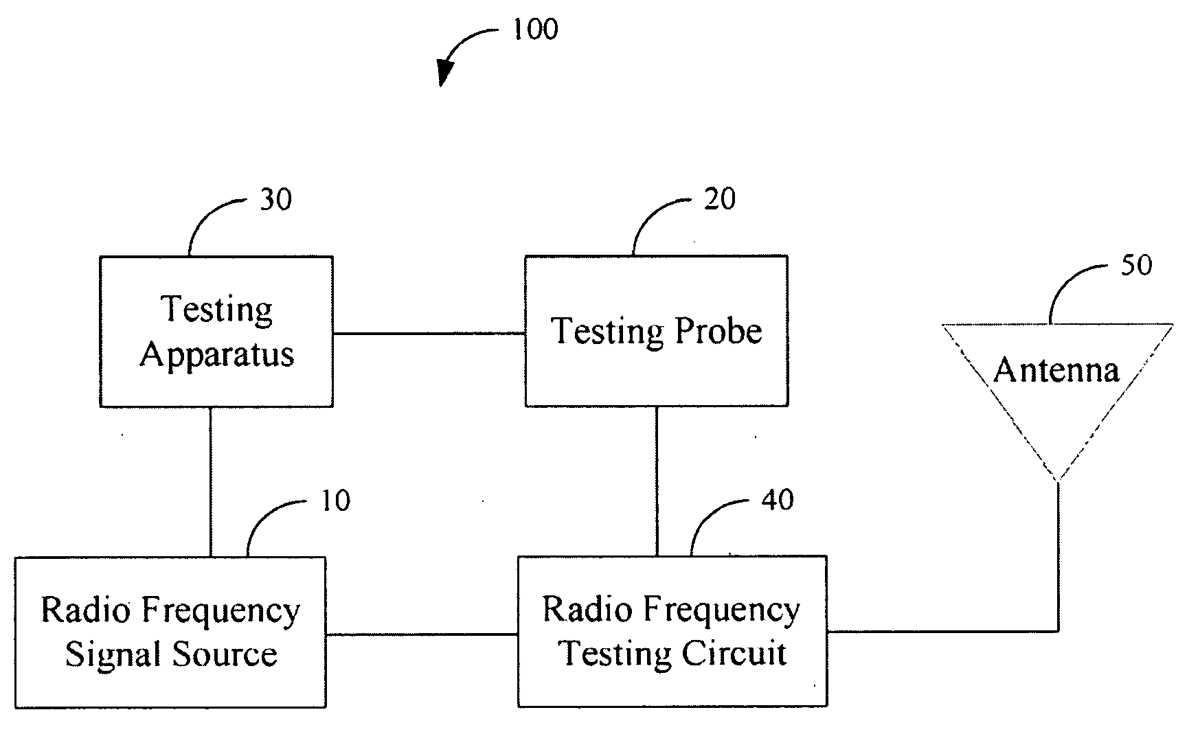
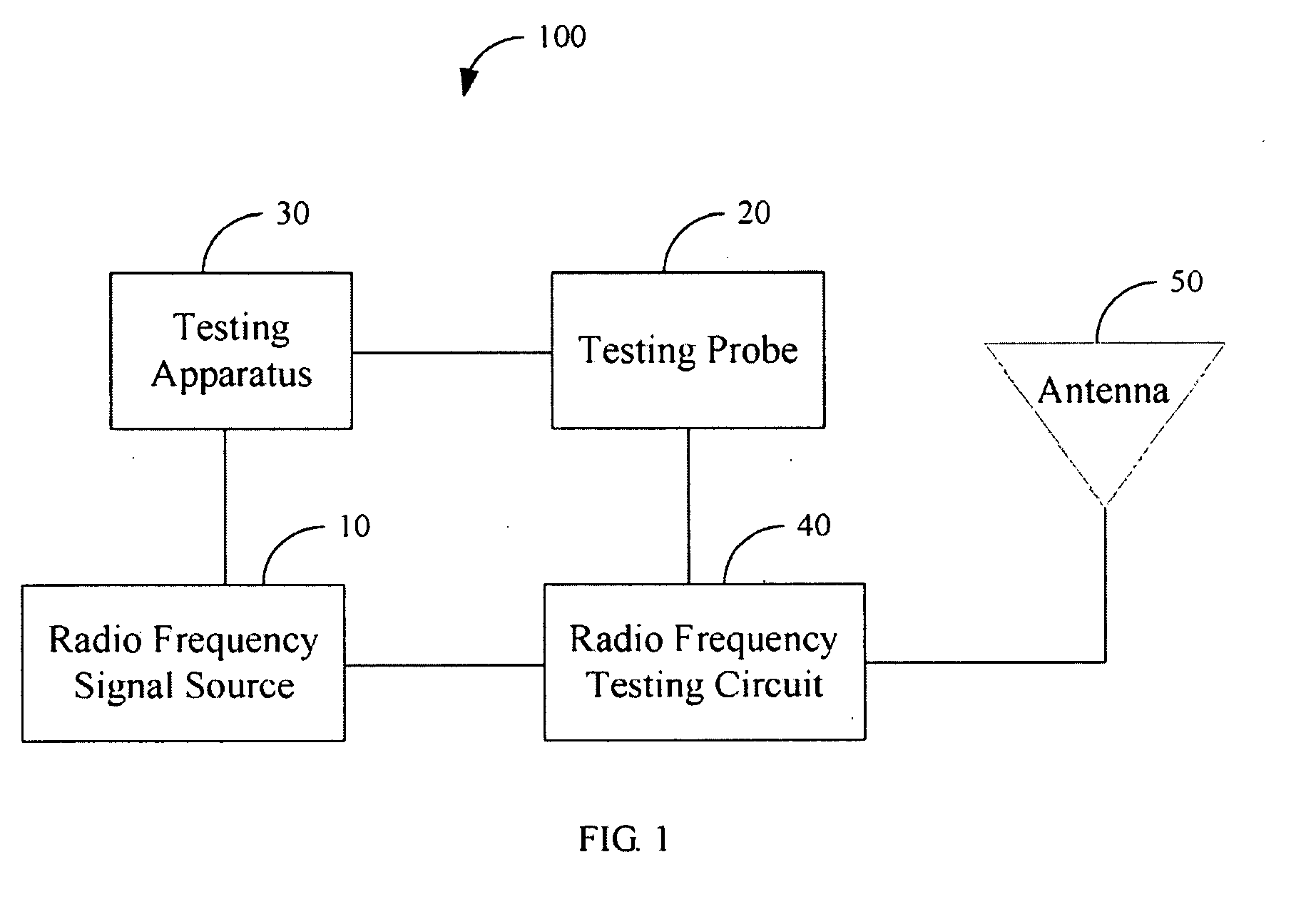
[0011]FIG. 1 is a block diagram of a radio frequency testing system 100 of an exemplary embodiment of the present invention. The radio frequency testing system 100 includes a radio frequency signal source 10, a testing probe 20, a testing apparatus 30, a radio frequency testing circuit 40, and an antenna 50.

[0012]The radio frequency signal source 10 generates radio frequency (RF) signals and transmits the RF signals to the radio frequency testing circuit 40.

[0013]The testing probe 20 is electrically connected to the radio frequency testing circuit 40 and the testing apparatus 30, and receives the RF signals from the radio frequency testing circuit 40. In the embodiment, the RF signals received by the testing probe 20 are designated as received RF signals.

[0014]The testing apparatus 30 receives the received RF signals from the testing probe 20, and tests the received RF signals to determine if a power of the antenna 50 is acceptable.

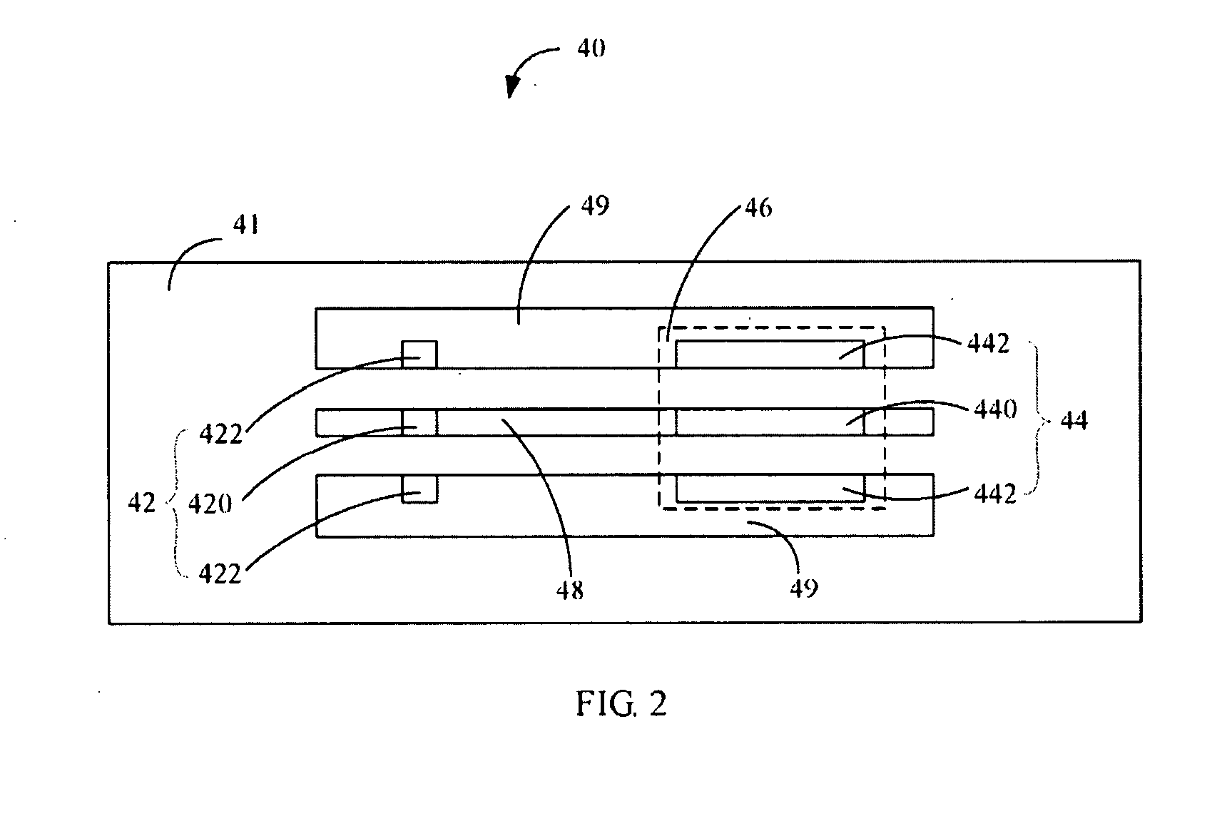
[0015]FIG. 2 is a schematic view of a radio frequen...


PUM


Abstract

A radio frequency (RF) testing system (100) includes a RF signal source (10) generating RF signals, an antenna (50), a RF testing circuit (40) disposed on a printed circuit board (PCB) (41), a testing probe (20) for receiving the RF signal from the RF testing circuit, and a testing apparatus (30) for testing the RF signals from the testing probe. The RF testing circuit includes a first pad (42), a second pad (44), a transmission line (48), and at least one ground portion (49) parallel to the transmission line. A distance between a first region defined by the first pad and a second region defined by the second pad positioned between the first region and the antenna is equal to one-fourth of the wavelength. During testing, the testing probe is electrically connected to the first pad, and the second pad is electrically connected to ground of the PCB.

Description

BACKGROUND [0001]1. Field of the Invention[0002]The invention relates to radio frequency testing, and particularly to a radio frequency testing system with a radio frequency testing circuit.[0003]2. Description of Related Art[0004]A radio frequency (RF) element, such as an antenna, is a key element of a wireless communication device. In order to improve quality and performance of the wireless communication device, the radio frequency element is often tested.[0005]Conventionally, during testing the of radio frequency element, a radio frequency connector is used. A socket of the radio frequency connector is arranged on the printed circuit board, and a plug or testing probe electrically connects a testing apparatus and the socket of the radio frequency via a cable. During testing, the socket of the radio frequency connector functions the same as a switch. Namely, the socket of the radio frequency connector can cut off input from the RF signal to the radio frequency element. Thus, all t...

Claims


Application Information

Patent Timeline
IPC IPC(8): G01R31/02
CPCH04B17/16
Inventor WU, CHENG-YUYAN, TAO
Owner NANNING FUGUI PRECISION IND CO LTD
Why Eureka
Try Eureka