High frequency device equipped with rectangular waveguide
a technology of rectangular waveguide and high frequency device, which is applied in the direction of waveguides, multiple-port networks, electrical devices, etc., can solve the problems of increased thickness of the device, and difficulty in manufacturing the device, and achieves the effect of thin body
- Summary
- Abstract
- Description
- Claims
- Application Information
AI Technical Summary
Benefits of technology
Problems solved by technology
Method used
Image
Examples
first embodiment
[0029]Referring to FIGS. 1-2A and 2B, a first embodiment will now be described.
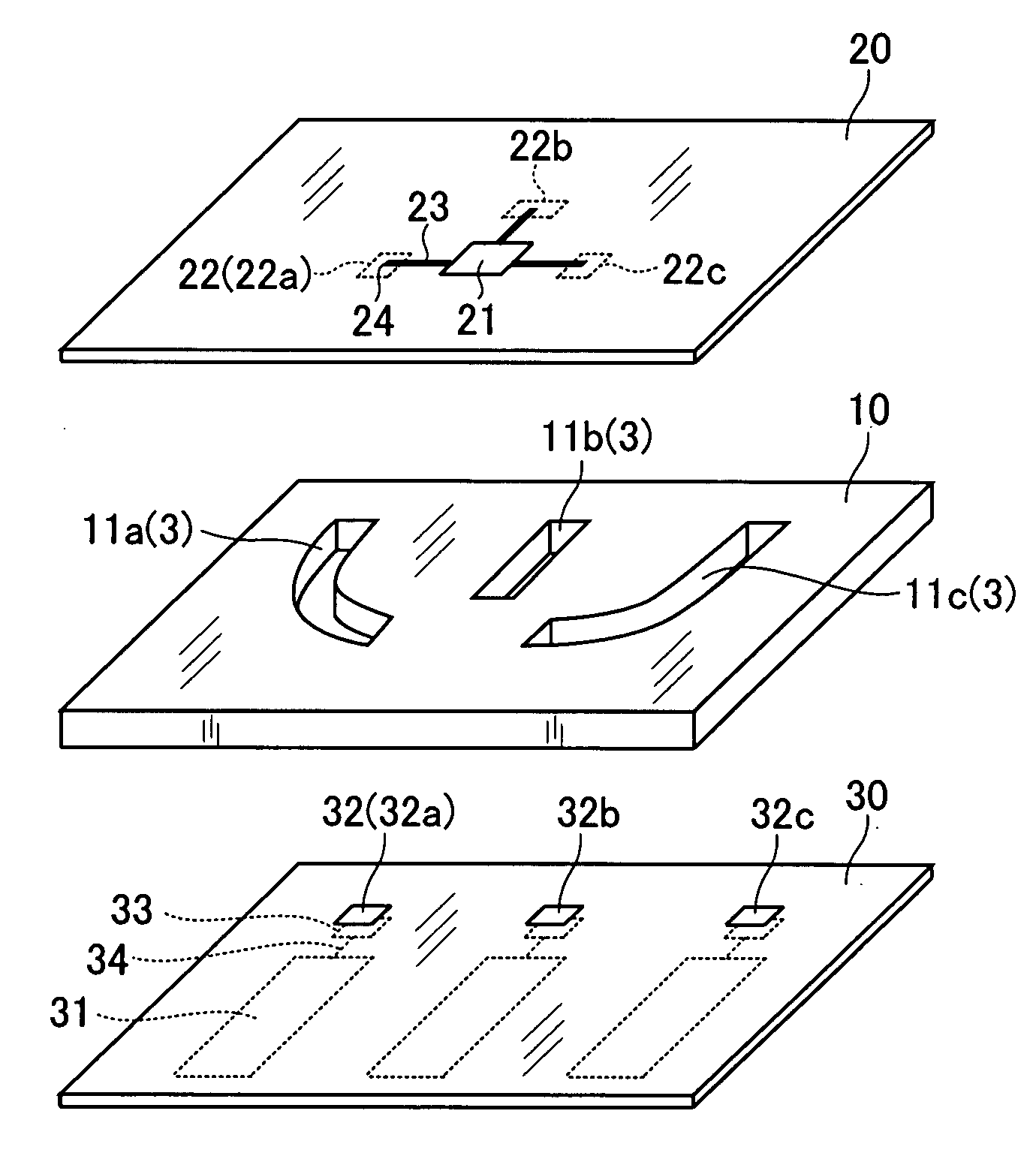
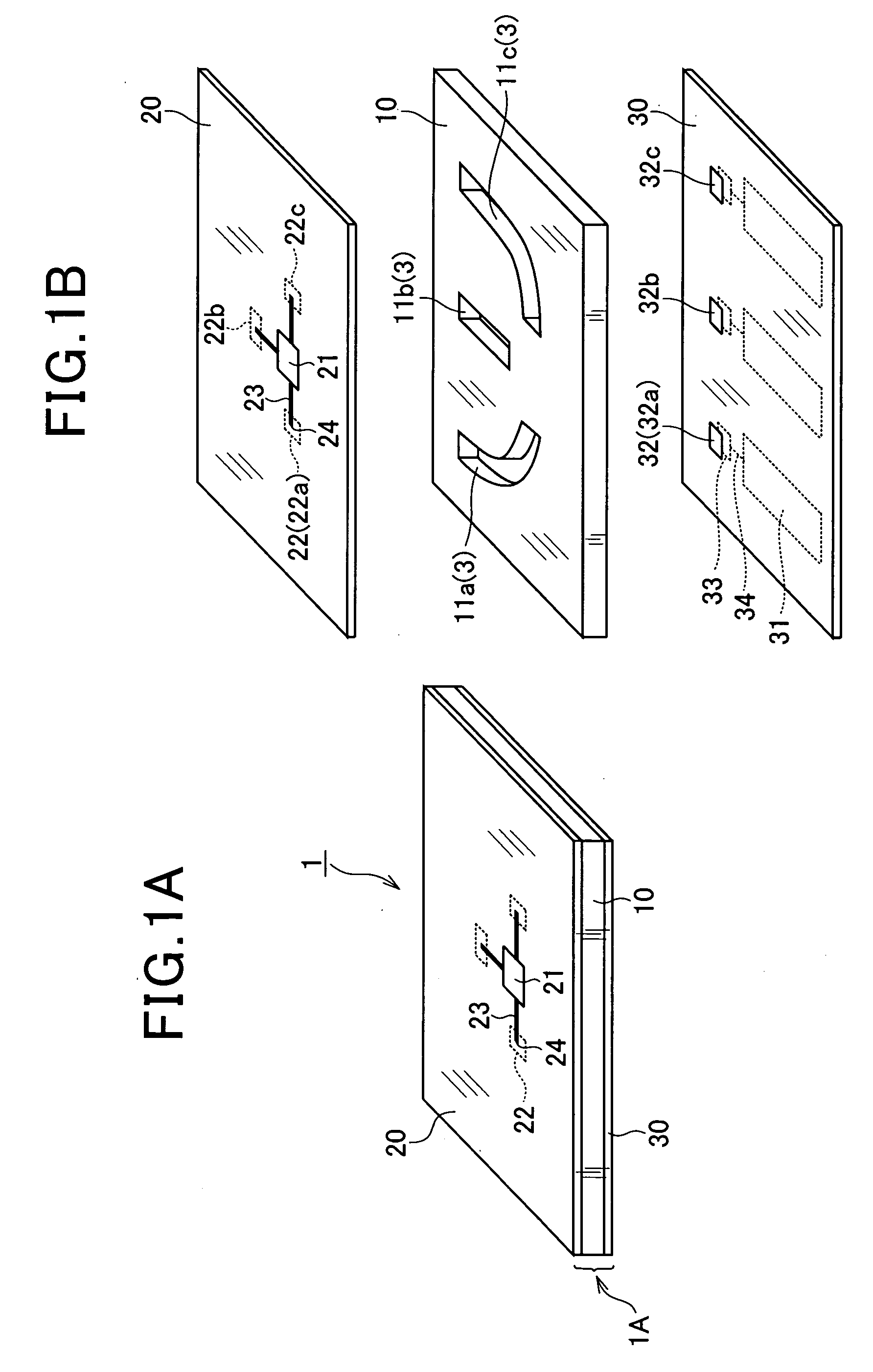
[0030]FIG. 1A is a perspective view showing an overall configuration of a high frequency signal transmitting device 1 to which the present invention is applied. FIG. 1B is an exploded perspective view showing the high frequency signal transmitting device 1.
[0031]The high frequency signal transmitting device 1, which serves as the high-frequency device according to the present invention, is applied to a radar device using millimeter waves and microwaves.
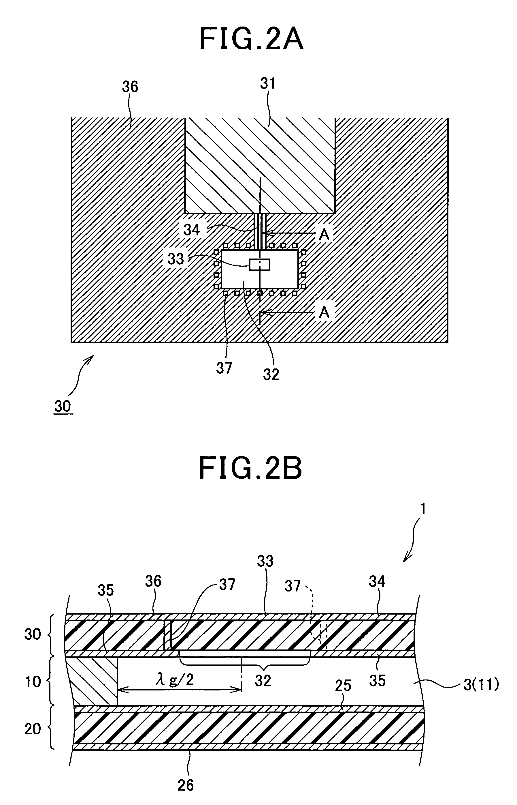
[0032]As shown in FIGS. 1A and 1B, the high frequency signal transmitting device 1 includes a waveguide plate 10, a first substrate 20, and a second substrate 30. A plurality (three according to the first embodiment) of through holes 11 (11a to 11c) are formed on the waveguide plate 10 so as to form a rectangular waveguide passage 3. The waveguide plate is made of metallic plate (e.g. conductor). The first substrate 20 and the second substrate 30 are attach...
second embodiment
[0044]Next, referring to FIGS. 3A and 3B, a second embodiment will now be described.
[0045]In this embodiment, only a configuration of the waveguide plate 10 differs from that of the waveguide plate 10 according to the first embodiment. Therefore, a portion of the configuration that differs will mainly be described.
[0046]FIG. 3A is a planar view showing a joint surface of the waveguide plate 10 at which the waveguide plate 10 and the first substrate 20 are joined.
[0047]As shown FIG. 3A, on the joint surface of the waveguide plate 10 at which the waveguide plate 10 and the first substrate 20 are joined, grooves 12 (12a to 12c) are arranged corresponding to respective through holes 11(11a to 11c). The grooves work as air passages that allow the air to flow between the rectangular waveguide passage 3 and outside space of the waveguide plate 10.
[0048]This groove 12 (12a to 12c) are formed such that end portions at a side of the through holes 11 are formed to be at portions that are nλg / 2...
third embodiment
[0054]Next, referring to FIGS. 4A-4C, a third embodiment will now be described.
[0055]A high frequency signal transmitting device 5 of the third embodiment is configured as a slot array antenna.
[0056]FIG. 4A is a planar view showing a configuration of the high frequency signal transmitting device 5. FIG. 4B is a cross-sectional view showing a section along the B-B line taken in FIG. 4A. FIG. 4C is a planar view showing a joint surface of the first substrate at which the waveguide plate and the first substrate are joined.
[0057]As shown in FIG. 4, the high frequency signal transmitting device 5 comprises a waveguide plate 40 which is made of metallic plate, having a through hole 41 used for a rectangular waveguide passage 7, and the first and second substrates 50, 60 which are joined to opposite side of the waveguide plate 40.
[0058]Among these, the first substrate 50 is made of resin in which various high frequency circuits are arranged on an opposite side of the joint surface of the w...
PUM
 Abstract
Description
Claims
Application Information
 - R&D
- Intellectual Property
- Life Sciences
- Materials
- Tech Scout
- Unparalleled Data Quality
- Higher Quality Content
- 60% Fewer Hallucinations
Browse by: Latest US Patents, China's latest patents, Technical Efficacy Thesaurus, Application Domain, Technology Topic, Popular Technical Reports.
© 2025 PatSnap. All rights reserved.Legal|Privacy policy|Modern Slavery Act Transparency Statement|Sitemap|About US| Contact US: help@patsnap.com


